Samsung Electronics
4-3
Troubleshooting
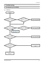
4-1-2 No Output
Check MAIN
PCB IC13 (4560) input and
output signal?
No Output
Check the AIC 2 working.
No
1
Check MAIN PCB
WIC1 (9830) and input and
output signal?
Yes
Yes
Yes
Check MICOM IC
(UIC1) and MICI MPEG
(ESS) signal?
Yes
Replace UIC1 and MIC1.
Check MAIN PCB
PCN1 Pin 1 ~ 4: +37V or 29V
and Pin 11 ~ 14: -37V
or -29V?
Check IC13 (4560) signal
input and signal pattern.
Check or replace SMPS.
Check WIC1(9830) signal
input and signal pattern.
Check signal input and
signal pattern or replace
SMPS.
Yes
No
No
No
No
Check MAIN PCB
ALD10, 11 red led is light?
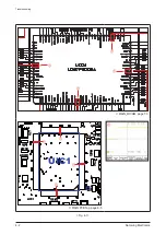
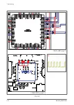
Refer to wave pattern
image of Fig. 4-2.
Summary of Contents for MAX-G55
Page 24: ...3 12 Samsung Electronics MEMO ...
Page 44: ...5 11 Samsung Electronics MEMO ...
Page 55: ...5 11 Samsung Electronics MEMO ...
Page 57: ...6 2 Samsung Electronics PCB Diagram 6 2 FRONT PCB Top 1 UCW2 USJ1 UCW1 UIC2 ...
Page 59: ...6 4 Samsung Electronics PCB Diagram 6 3 FRONT PCB Bottom FIC1 UIC2 UCW1 USJ1 UCW2 ...
Page 64: ...Samsung Electronics 6 9 PCB Diagram 6 6 SMPS PCB Top CON2 CN1 UB1 CON3 UM1 ...
Page 65: ...6 10 Samsung Electronics PCB Diagram 6 7 SMPS PCB Bottom CON2 CN1 UB1 CON3 UM1 ...
Page 73: ...7 8 Samsung Electronics MEMO ...

