


8 English
INS
TALLA
TION
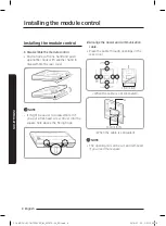
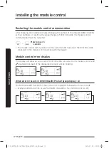
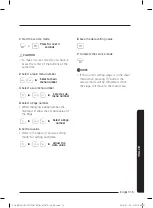
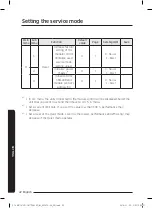
Installing the module control
CAUTION
• The power and communication wire of
the module control and the power wire
of DVM CHILLER should be installed
separately.
– Electrical interference may cause the
module control to malfunction.
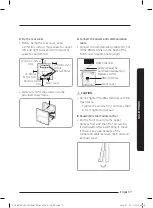
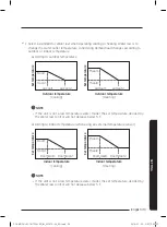
• Make sure to connect the power
and communication cable through
a protection tube since the cable is
exposed to an outdoor area.
• When installing the module control on
the wall, consider of the size of the wire
hole, and select a wire with a proper
thickness.
• Wire for module control power and
communication:
– When installing the module control
by embedding it on the wall, install
it according to U-terminal cable
specification.
– If you install the module control by
using two pieces of PVC wire, remove
the 30 cm(12 inch) of the sheath of
the cable and install it only with the
two pieces of wires. (Recommended
specification: AWG20)
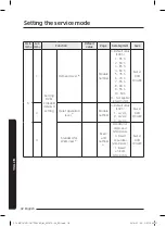
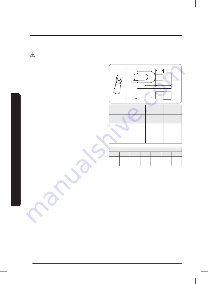
• Specification of compressed U-terminal
for connecting module control PBA
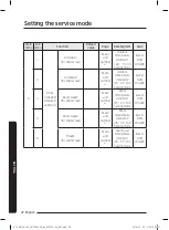
W
t
F
L
G
E
Ø
D
Stud
Wire range for
connection
Rated size Stud size
AWG
mm
2
(inch
2
)
mm
2
(inch
2
)
mm(inch)
22 ~ 16
0.25 ~
1.65
(0.0003 ~
0.0025)
1.5
(0.0023)
3 (0.1181)
Basic size [mm(inch)]
t
ØD
G
E
F
W
L
0.7
(0.0275)
3.8
(0.1496)
10.0
(0.3937)
4.5
(0.1771)
6.5
(0.2559)
6.0
(0.2362)
21.2
(0.8346)
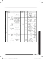
※
The maximum wiring length for power
and communication: 200 m(656.17 ft)
• Tighten the fixing screws to the PCB
terminal with less than 6 N·cm torque.
• If the screws are tightened with too
much force, the screw thread will be
damaged.
SOL MODULE CONTROLLER_IM_05747A-00_EN.indd 8
2016-01-20 오후 12:00:18


