background image

MICROWAVE OVEN

SERVICE

Manual

MICROWAVE OVEN

CONTENTS

1. Precaution .......................................... 1

2. Specifi cations .................................... 3

3. Operating Instructions....................... 4

4. Disassembly and Reassembly............5

5. Alignment and Adjustment..................9

6. Troubleshooting ............................... 13

7. Exploded Views and Parts List ........15

8. PCB Diagrams .................................. 19

9. Schematic Diagrams ........................ 21

MD1200WD

SEA

Summary of Contents for MD1200WD

Page 1: ...VEN CONTENTS 1 Precaution 1 2 Specifications 3 3 Operating Instructions 4 4 Disassembly and Reassembly 5 5 Alignment and Adjustment 9 6 Troubleshooting 13 7 Exploded Views and Parts List 15 8 PCB Diagrams 19 9 Schematic Diagrams 21 MD1200WD SEA ...

Page 2: ...ual is a property of Samsung Electronics Co Ltd Any unauthorized use of Manual can be punished under applicable International and or domestic law Samsung Electronics Co Ltd May 2004 Printed in Korea Code No DE68 03544A ...

Page 3: ...ction within the microwave generating compartments check the magnetron wave guide or transmission line and cavity for proper alignment integrity and connections d Any defective or misadjusted components in the interlock monitor door seal and microwave generation and transmission systems shall be repaired replaced or adjusted by procedures described in this manual before the oven is released to the...

Page 4: ...es while repairing an MWO 11 To avoid any possible radiation hazard replace parts in accordance with the wiring diagram Also use only the exact replacements for the following parts Primary and secondary interlock switches interlock monitor switch 12 If the fuse is blown by the Interlock Monitor Switch Replace all of the following at the same time Pri mary door sensing switch and power relay as wel...

Page 5: ...ged about 30 seconds after disconnection Short the negative terminal of the high voltage capacitor to to the oven chassis Use a screwdriver 3 High voltage is maintained within specified limits by close tolerance safety related components and adjustments If the high voltage exceeds the specified limits check each of the special com ponents Fig 1 1 Discharging High Voltage Capacitor Touch chassis grou...

Page 6: ...ENCY MAGNETRON COOLING METHOD OUTSIDE DIMENSIONS NET WEIGHT SHIPPING WEIGHT 99 MINUTES 99SECONDS 120V 60Hz AC MICROWAVE 1 500W FROM 100 TO 1000W 10 LEVEL POWER ICE 705 TEST PROCEDURE 2 450MHz OM75S 20 COOLING FAN MOTOR 466 W x 336 H x 511 D 35 2 lbs 40 8 lbs 2 1 Table of Specifications ...

Page 7: ...unts and power levels other than high Press this pad to set a power level other than high Sets kitchen or convenience timer Sets current time 8 Sound Button 9 Pause Cancel 10 Start 11 Handy Helper Kids Meals Snack Bar 12 Auto Reheat 13 More Button Sets sound on or off Press to pause oven or correct a mistake Press to start cooking Selects type of dish to be reheated Shows type and quantity of food...

Page 8: ...netron gasket in the correct position and make sure the gasket is in good condition 1 Discharge the high voltage capacitor 2 Disconnect all the leads 3 Remove the screw 4 Reconnect the leads correctly and firmly PRECAUTION Servicemen should remove their watches whenever work ing close to or replacing the magnetron PRECAUTION There exists HIGH VOLTAGE ELECTRICITY with high current capabilities in th...

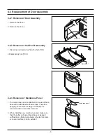
Page 9: ...4 3 3 Removal of Membrane Panel 1 The membrane panel is attached to the escutcheon base with doublefaced adhesive tape Therefore applying hot air such as using of hair dryer is recommended for smoother removal 3 When installing new membrane panel make sure that the surface of escutcheon base is cleaned sufficiently so that any problems shorted contacts or uneven surface can be avoided DOOR C DOOR E...

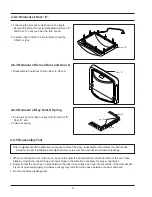
Page 10: ...se plate with a screw driver NOTE Bring the spare screw from service center COVER FIXING SCREW MACHINE SCREW 6006 0011110 1 Disconnect the oven from the power source 2 When 15A fuse blows out by the operation of interlock monitor switch failure replace the primary interlock switch door sensing switch monitor switch and power relay 3 When the above three switches operate properly check if any other...

Page 11: ...r A 4 6 5 Reassembly Test 1 When mounting the door to the oven be sure to adjust the door parallel to the bottom line of the oven face plate by moving the upper hinge and lower hinge in the direction necessary for proper alignment 2 Adjust so that the door has no play between the inner door surface and oven front surface If the door assem bly is not mounted properly microwave energy may leak from ...

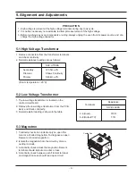
Page 12: ...e capacitor 1 Continuity checks can indicate only an open fila ment or a shorted magnetron To diagnose an open filament or shorted magnetron 2 Isolate the magnetron from the circuit by discon necting its leads 3 A continuity check across the magnetron filament terminals should indicate one ohm or less 4 A continuity check between each filament terminal and magnetron case should read open circuit 1 The...

Page 13: ...en mounting the Latch Body to the oven assem bly adjust the Latch Body by moving it so that the oven door will not have any play in it Check for play in the door by pulling the door assembly Make sure that the latch keys move smoothly after adjustment is completed Completely tighten the screws holding the Latch Body to the oven assembly 4 Reconnect to Monitor switch and check the continu ity of th...

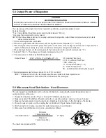
Page 14: ...mperature Mc Cylindrical borosilicate glass weight 45 7 Normal temperature rise for this model is 9 3 C to 10 5 C at HIGH NOTE 1 Variations or errors in the test procedure will cause a variance in the temperature rise Additional power test should be made if temperature rise is marginal 5 8 Output Power of Magnetron The microwave heat distribution can be checked indirectly by measuring the water te...

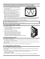
Page 15: ...oor seam is taken near a corner of the door keep the probe perpendicular to the areas making sure that the probe end at the base of the cone does not get closer than 5cm to any metal If it gets closer than 5cm erroneous readings may result 5 Measured leakage must be less than 4mW cm2 after repair or adjustment Maximum allowable leakage is 5mW cm2 4mW cm2 is used to allow for measurement and meter ...

Page 16: ... main Timer starts countdown but no microwave oscillation No heat while oven lamp and fan motor turn on 1 Off alignment of latch switches 2 Open or loose connection of high voltage circuit especially magnetron filament circuit NOTE Large contact resistance will bring lower magnetron filament voltage and cause magnetron to lower out put and or intermittent oscillation 3 Defective high voltage compone...

Page 17: ...d 1 Loose fan and fan motor 2 Loose screws on H V Transformer 3 Shorted H V Diode Tighten screws of fan motor Tighten screws of H V Transformer Replace H V Diode Turntable motor does not rotate 1 Open or loose wiring of turntable motor 2 Defective turntable motor Replace turntable motor Oven stops operation dur ing cooking 1 Open or loose wiring of Secondary interlock switch 2 Operation of thermal...

Page 18: ... 15 7 Exploded Views and Parts List 7 1 Exploded Views T001 M048 M038 T017 H018 M020 M001 M039 M040 M035 W002 M015 B006 B018 B001 B001 B011 B002 B010 M047 M049 M036 M029 M041 M030 ...

Page 19: ...SMF 1000UA 120V 60HZ MD 1 M029 DE47 20173A THERMOSTAT PW 2N 90 60 30 187Y 250V7 5A 1 CAVITY M030 DE47 00002B THERMOSTAT PW2N 100 110 187H 3 1 MGT M035 OM75P 20 ERHN ASSY MAGNETRON OM75P 20 ERHN 1 M036 DE07 00006A LAMP INCANDESCENT 125V 25W ORG TERMI 1 M038 DE26 00097A TRANS H V SHV UT10KA 120V 60HZ 2250V 3 2 1 M039 2501 001016 C OIL 950nF 2 1KV BK 35x54x80 20mm 1 M040 DE61 00643A BRACKET HVC MR89 ...

Page 20: ...G 1 1 D006 DE64 01170A DOOR C MD1200WD PP TB53 BLK 1 2 1 D007 DE61 00193A SPRING KEY M1733 HSWR D5 5 19 1 4 T0 6 1 DOOR E KEY DOOR D011 DE64 00891A KEY DOOR MW8ROWC POM F20 02 T2 0 BLK 1 DOOR E D049 DE31 10162A ASSY DOOR MD1200WD PURE WHITE 1 2 ROUND 1 D078 DE96 00401A ASSY DISPLAY KIT MD1200WD DISPLAY KIT 1 SCREEN DOOR S N A SERVICE NOT AVAILABLE D007 D004 D011 D006 D002 D049 D078 ...

Page 21: ...60 10051A SCREW TAP PH MSWR PH M4 L6 1 DRIVE MOTOR 6002 000239 SCREW TAPPING TH 2S M4 L8 ZPC YEL SM20C 1 BKT MGT 6002 001170 SCREW TAPPING FH STAR 2 M4 L12 SIL SWRCH18A 1 B LATCH 6002 001174 SCREW TAPPING FH 2S M4 L12 NI PLT MSWR 4 O P SIDE 6002 001325 SCREW TAPPING TH TORX 2S M4 L12 ZPC YEL 2 O P BACK 6006 001170 SCREW TAPPING WS TH M4 L10 ZPC YEL 1 PCB GROUND 6006 001170 SCREW TAPPING WS TH M4 L...

Page 22: ..._RED 3 5 7 1 C01 10K 5V 1000uF C15 1nF 12V R13 C16 1nF C07 C14 100nF 100nF 100nF C05 C06 100nF 100nF TR08 KRA226 AT C04 KSR1005 TR01 C17 1nF KRA226 AT FH 51H FUSE1 TR09 KRA226 AT TR10 TR02 R17 90 9K KSR1005 1N4148M D03 10D471 ZNR1 358A IC05 VCC 8V GND DGND 1 2 3 4 5 10uF C13 5V SMW250 05V_WHT CN05 100K R19 2 3 4 12V 8V 2K R18 SMW250 04V_RED CN04 1 CBE2220BA R07 1K 8V BZ01 KRA226 AT TR12 390M PTC1 ...

Page 23: ...C KA7533 DIP 1 IC03 DE09 00054A IC MICOM TMP87PH47U OTP OTP 16K QFP 1 IC01 1203 001037 IC POSI FIXED REG 78L05 SOT 89 3P 185MIL PLASTIC 1 IC02 2001 000273 R CARBON 100KOHM 5 1 8W AA TP 1 8X3 2MM 1 R19 2001 000290 R CARBON 10KOHM 5 1 8W AA TP 1 8X3 2MM 2 R05 R13 2001 000429 R CARBON 1KOHM 5 1 8W AA TP 1 8X3 2MM 1 R01 2001 000577 R CARBON 2KOHM 5 1 8W AA TP 1 8X3 2MM 3 R03 R04 R06 2001 000734 R CARB...

Page 24: ...n BLK BLU BLK RED RED RED RED BLU RED ORG ORG BLU BLK BLK BLK MAGNETRON HIGH VOLTAGE DIODE TO CHASSIS FA F HIGH VOLTAGE TRANSFORMER POWER RELAY DOOR SENSING SWITCH BOTTOM MONITOR SWITCH CENTER BLK WHT WHT SECONDARY SWITCH TOP HIGH VOLTAGE CAPACITOR RED ORG WHT SYMBOL COLOR BLU BLK RED ORANGE WHITE BLUE BLACK ...

Reviews: