background image

4. Disassembly and Reassembly

4-1 Replacement of Magnetron, Motor Assembly and Lamp

Remove the magnetron including the shield case, permanent magnet, choke coils and capacitors (all of
which are contained in one assembly).

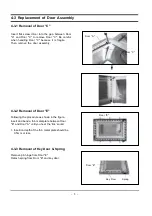
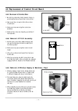
1. Disconnect all lead wires from the magnetron and lamp.
2. Remove a screw securing air cover.
3. Remove the air cover.
4. Remove screws securing the magnetron to the wave guide.
5. Take out the magnetron very carefully.
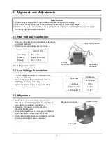
6. Remove tow from the back panel of fan motor assembly.
7. Take out the fan motor assembly.
8. Remove the oven lamp by rotating to pull out from hole of air cover.

NOTE1: When removing the magnetron, make sure that its antenna does not hit any adjacent

parts, or it may be damaged.

NOTE2: When replacing the magnetron, be sure to remount the magnetron gasket in the correct

position and make sure the gasket is in good condition.

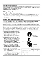
4-2 Replacement of High Voltage Transformer

1. Discharge the high voltage capacitor.
2. Disconnect all the leads.
3. Remove the mounting bolts.
4. Reconnect the leads correctly and firmly.

PRECAUTION

Servicemen should remove their watches whenever
working close to or replacing the magnetron.
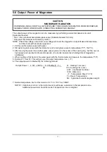
PRECAUTION

There exists HIGH VOLTAGE ELECTRICITY with high current capabilities in the circuits of the HIGH
VOLTAGE TRANSFORMER secondary and filament terminals. It is extremely dangerous to work on or near
these circuits with the oven energized.
DO NOT measure the voltage in the high voltage circuit including filament voltage of magnetron.

Summary of Contents for ME1260SB

Page 1: ...ROWAVE OVEN 1 Precaution 2 Specifications 3 Operating Instructions 4 Disassembly and Reassembly 5 Alignment and Adjustments 6 Troubleshooting 7 Exploded Views and Parts List 8 PCB Diagrams 9 Schematic Diagrams Manual ME1260SB SEA SAM0016 ...

Page 2: ...s and latches 5 evidence of dropping or abuse c Before turning on microwave power for any service test or inspection within the microwave generating compartments check the magnetron wave guide or transmission line and cavity for proper alignment integrity and connections d Any defective or misadjusted components in the interlock monitor door seal and microwave generation and transmission systems s...

Page 3: ...uld remove their watches while repairing an MWO 11 To avoid any possible radiation hazard replace parts in accordance with the wiring diagram Also use only the exact replacements for the following parts Primary and secondary interlock switches interlock monitor switch 12 If the fuse is blown by the Interlock Monitor Switch Replace all of the following at the same time Secondary door sensing switch...

Page 4: ...e oven and discharge the high voltage capacitor See Figure 1 1 2 The high voltage capacitor remains charged about 30 seconds after disconnection Short the negative terminal of the high voltage capacitor to to the oven chassis Use a screwdriver 3 High voltage is maintained within specified limits by close tolerance safety related components and adjustments If the high voltage exceeds the specified ...

Page 5: ...ONSUMPTION OUTPUT POWER OPERATING FREQUENCY MAGNETRON COOLING METHOD OUTSIDE DIMENSIONS NET WEIGHT SHIPPING WEIGHT 99 MINUTES 99SECONDS 120V 60Hz AC MICROWAVE 1 550W 1050W 10 LEVEL POWER 2 450MHz OM75PH 31 ESS COOLING FAN MOTOR 2019 32 W x 1145 64 H x 161 4 D 33 lbs 36 lbs ...

Page 6: ...s Meals Snack Bar Selects type of dish to be reheated Auto Reheat Selects type of dish to be reheated More Less Increase or decrease cooking time Kitchen Timer Sets kitchen or convenience timer Start Press to start cooking Sound Button Sets sound on or off Instant Cook Buttons Instant settings to cook popular foods Auto Defrost Sets weight of food to be defrosted Number Buttons Sets cooking times ...

Page 7: ...at its antenna does not hit any adjacent parts or it may be damaged NOTE2 When replacing the magnetron be sure to remount the magnetron gasket in the correct position and make sure the gasket is in good condition 4 2 Replacement of High Voltage Transformer 1 Discharge the high voltage capacitor 2 Disconnect all the leads 3 Remove the mounting bolts 4 Reconnect the leads correctly and firmly PRECAU...

Page 8: ... remove the door assembly 4 3 2 Removal of Door E Following the procedure as shown in the figure insert and bend a thin metal plate between Door E and Door A until you hear the tick sound 1 Insertion depth of the thin metal plate should be 0 5mm or less 4 3 3 Removal of Key Door Spring Remove pin hinge from Door E Detach spring from Door E and key door Door E Key Door Spring Door E Door A Door C ...

Page 9: ...eck if any other part such as the control circuit board blower motor or high voltage transformer is defective 4 5 Replacement of Drive Motor 1 Take out the glass tray guide roller from cavity 2 Turn the oven upside down to replace the drive motor 3 Remove a screw securing the drive motor cover or disconnect the drive motor cover from base plate by nipper 4 Disconnect all the lead wires from the dr...

Page 10: ...the Ass y control box 4 When reconnecting the FPC connector make sure that the holes on the connector are properly engaged with the hooks on the Plastic Fastener 4 6 3 Removal of Window Display Membrane Panel 1 Window display should not be disassembled as its mounting tabs will be broken If repair work is difficult replace with Ass y control panel 2 The membrane key board is attached to the escutc...

Page 11: ...on from the circuit by disconnecting its leads 3 A continuity check across the magnetron filament terminals should indicate one ohm or less 4 A continuity check between each filament terminal and magnetron case should read open Primary Terminals Filament Terminals Secondary Terminal Magnetron Antenna Gasket Plate Cooling Fins PRECAUTION 1 High voltage is present at the high voltage terminals durin...

Page 12: ...No specific adjustment during installation of Primary switch Secondary switch and Monitor switch to the latch body is necessary 3 When mounting the Latch Body to the oven assembly adjust the Latch Body by moving it so that the oven door will not have any play in it Check for play in the door by pulling the door assembly Make sure that the latch keys move smoothly after adjustment is completed Comp...

Page 13: ...3 seconds included as a holding time of magnetron oscillation 4 When heating is finished stir the water again with the thermometer and measure the temperature T2 5 Subtract T1 from T2 This will give you the water temperature rise T 6 The output power is obtained by the following formula Output Power 4 187 x 1000 x T 0 55xMcx T2 T0 41 Heating Time sec 38 38 Counting Time sec 4 187 Coefficient for W...

Page 14: ...n at the highest power level 4 Set survey meter dual ranges to 2 450MHz 5 Using the survey meter and spacer cone as described above measure near the opening of magnetron the surface of the air guide and the surface of the wave guide as shown in the following photo but avoid the high voltage components The reading should be less than 4mW cm2 5 11 Note on Measurement 1 Do not exceed the limited scal...

Page 15: ...tion procedure Replace PCB main Timer starts countdown but no microwave oscillation No heat while oven lamp and fan motor turn on 1 Off alignment of latch switches 2 Open or loose connection of high voltage circuit especially magnetron filament circuit NOTE Large contact resistance will bring lower magnetron filament voltage and cause magnetron to lower output and or intermittent oscillation 3 Def...

Page 16: ... main Loud buzzing noise can be heard 1 Loose fan and fan motor 2 Loose screws on H V Transformer 3 Shorted H V Diode Tighten screws of fan motor Tighten screws of H V Transformer Replace H V Diode Turntable motor does not rotate 1 Open or loose wiring of turntable motor 2 Defective turntable motor Replace turntable motor Oven stops operation during cooking 1 Open or loose wiring of Secondary inte...

Page 17: ...ed Views MM01 MM22 MM102 MM16 MM07 MM03 MM13 MM29 MM30 MM31 MM14 MM18 MM19 MM20 MM27 MM28 MM06 MM17 MM52 MM08 MM10 MM09 MB01 MB05 MB03 MB08 MB04 MB02 MM17 MC01 MD01 MD07 MC05 MC04 MC02 MC03 MC06 MC07 MD10 MD06 MD05 MD04 MD11 MD02 MD03 MM34 MM55 ...

Page 18: ...RG B L 2 1 MM102 DE63 00021A CUSHION HVT MW6693G EPDM EPDM T10 5 W30 1 MM13 DE66 90113A LEVER DOOR PP TB53 GH41 T2 5 12g NT 1 MM14 DE26 00061B TRANS H V SHV U11KA_R 120V 60HZ 2300V 3 1 MM16 DE71 00015A COVER CEILING CE2933 T0 3 W114 2 L121 1 MM17 DE47 20033A THERMOSTAT PW 2N 80 70 125V15A 250V7 5A 1 CAVITY MM17 DE47 20173A THERMOSTAT PW 2N 90 60 30 187Y 250V7 5A 1 MGT MM18 DE74 20015G TRAY COOKING...

Page 19: ...SAN SMG 1 MC07 RA N2LED1 32 ASSY PCB PARTS ME1030SB 120V60HZ 1 MD01 ASSY DOOR ME1260SA XAA SILVER S2 DESIGN 1 S N A MD02 DE64 00185C DOOR A ME1260SA XAA ABS SILVER 1 1 MD03 DE63 00042A SCREEN DOOR CLEAR MW1250WA NC 12 PET T0 1 MD04 DE94 00428A ASSY DOOR E COATING MW1250WA NC 12 BLK 1 MD05 DE64 00248A FILM DOOR PE PC T0 15 178 5 306 1 MD06 DE64 00184A DOOR C MW1250WA PP BLK 1 2CUFT NC200 1 MD07 DE6...

Page 20: ...AN DE60 10070A SCREW TAP TH FEFZY 2 SLOT TH M4 L12 1 TCO DE60 10080B SCREW WASHER 2S SWRCH18A ZP2 PH PI5 L10 4 MGT DE60 10080B SCREW WASHER 2S SWRCH18A ZP2 PH PI5 L10 4 TNS HV DE60 10082H SCREW A 2S 4X12 TOOTHED 2 BD LT DE60 10082H SCREW A 2S 4X12 TOOTHED 1 P C EA DE60 10082H SCREW A 2S 4X12 TOOTHED 2 PN OUT DE60 10082H SCREW A 2S 4X12 TOOTHED 1 S M EA DE60 10098A SCREW ASSY TAP TITE GLD SWRCH18A ...

Page 21: ... 8 P C B Diagrams 8 1 P C B Diagrams ...

Page 22: ...P 1 PTC1 1405 000001 VARISTOR 470V 1250A 14x7 5mm TP 1 ZNR1 2001 000118 R CARBON S 180OHM 5 1 2W AA TP 2 4X6 4MM 3 R01 02 03 2007 000033 R CHIP 0OHM 5 1 8W DA TP 3216 2 J10 11 2007 000282 R CHIP 100KOHM 5 1 10W DA TP 2012 1 R28 2007 000300 R CHIP 10KOHM 5 1 10W DA TP 2012 4 R11 13 14 17 2007 000468 R CHIP 1KOHM 5 1 10W DA TP 2012 5 R06 08 10 15 2007 000572 R CHIP 220OHM 5 1 10W DA TP 2012 1 R16 20...

Page 23: ...ADS OR AS NOTED ON SPECIAL LEADS POWER MUST BE DISCONNECTED BEFORE SERVICING THIS APPLIANCE BLK BLU BLK RED RED RED RED WHT BLK RED WHT ORG ORG RED BLU BLU MAGNETRON HIGH VOLTAGE DIODE TO CHASSIS FA F HIGH VOLTAGE TRANSFORMER POWER RELAY DOOR SENSING SWITCH BOTTOM MONITOR SWITCH CENTER BLK WHT SECONDARY SWITCH TOP HIGH VOLTAGE CAPACITOR RED ORG WHT SYMBOL COLOR BLU BLK RED ORANGE WHITE BLUE BLACK ...

Reviews: