background image

1. Precaution

2. Product Specification

3. Disassembly and Reassembly
4. Troubleshooting
5. PCB Diagrams
6. Wiring Diagrams
7. Schematic Diagrams

BASIC MODEL :   GE83KRQW-1/BW


MODEL :  

MG23J5133A

MODEL CODE :  MG23J5133A

K

/

EF

Summary of Contents for MG23J5133AK

Page 1: ...recaution 2 Product Specification 3 Disassembly and Reassembly 4 Troubleshooting 5 PCB Diagrams 6 Wiring Diagrams 7 Schematic Diagrams BASIC MODEL GE83KRQW 1 BW MODEL MG23J5133AK MODEL CODE MG23J5133AK EF ...

Page 2: ...Assembly and Lamp 10 3 3 Replacement of High Voltage Transformer 13 3 4 Replacement of Door Assembly 15 3 5 Replacement of Drive Motor 16 3 6 Replacement of Control Circuit Board 17 3 7 Replacement of Grill heater 18 4 Troubleshooting 19 4 1 Parts checking method 19 4 2 Information Code Numbering Rule 20 4 3 Information Code List 21 4 4 Electrical Malfunction 22 5 PCB Diagrams 25 5 1 PCB Diagrams ...

Page 3: ...damage 4 Damage to or loosening of hinges and latches 5 Evidence of dropping or abuse c Before turning on microwave powerfor any service test or inspection within the microwave generating compartments check the magnetron wave guide or transmission line and cavity for proper alignment integrity and connections d Any defective or misadjusted components in the interlock monitor door seal and microwav...

Page 4: ...e fuse is blown by the Interlock Monitor Switch Replace all of the following at the same time Primary door sensing switch and power relay as well as the Interlock Monitor Switch The correct adjustment of these switches is described elsewhere in this manual Make sure that the fuse has the correct rating forthe particular model being repaired 13 Design Alteration Warning Use exact replacement parts ...

Page 5: ...ewdriver 3 High voltage is maintained within specified limits by close tolerance safety related components and adjustments If the high voltage exceeds the specified limits check each of the special components H V Diode Short H V Capacitor PRECAUTION There exists HIGH VOLTAGE ELECTRICITY with high current capabilities in the circuits of the HIGH VOLTAGE TRANSFORMER secondary and filament terminals ...

Page 6: ...orfully coated with Ceramic Enamel offers solid surface that neverscratches and cracks So you can enjoy the same new interioreven afterlong use Moreover it prevents the bacteria and the sooth surface It is easy to clean as well The significantly highercooking temperature and animal protein can cause severe discoloration and cleaning issuse But the Ceramic Enamel Interiorprevents all of them Aesthe...

Page 7: ...0 8 Cu ft Dimension Outside 489 x 275 x 372mm 489 x 275 x 354mm W x H x D Cavity 330 x 211 x 324mm 330 x 211 x 324mm Weight Net 12 5 kg 13 5 kg Gross 14 0 kg 15 0 kg Export Zone RUSSIA FRANCE Feature MWO Mode 1 MW YES YES Grill Mode 1 GRILL YES YES Combi Mode 1 MW GRILL YES 300W 450W 600W YES 300W 450W 600W Auto Cook 1 RUSSIAN MENUS YES 27 YES 27 2 HEALTHY COOKING YES 20 YES 20 3 SOUP DRINKS YES 1...

Page 8: ...his document can not be used without Samsung s authorization 2 Specifications 2 3 Accessory Item Description Code NO Q ty Assy Guide Roller DE97 00193D 1 Tray cooking DE74 20102D 1 Rack Wire DE74 70071D 1 ...

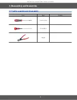
Page 9: ...9 This document can not be used without Samsung s authorization Tool Type Remark 7mm vox driver Screwdriver Nipper 3 Disassembly and Reassembly 3 1 Tool forassembly and disassembly ...

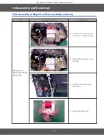
Page 10: ...mbly and Lamp Remove the magnetron including the shield case permanent magnet choke coils and capacitors all of which are contained in one assembly Parts Explaination Photo Explaination Magnetron MotorAssembly and Lamp 1 Disconnect all lead wires from the magnetron and lamp 2 Remove a screw securing air cover 3 Remove the air cover ...

Page 11: ...sembly 3 2 Disassembly of Magnetron MotorAssembly and Lamp Parts Explaination Photo Explaination Magnetron MotorAssembly and Lamp 4 Remove screws securing the magnetron to the wave guide 5 Take out the magnetron very carefully 6 Remove two nuts from the back panel 7 Take out the fan motor ...

Page 12: ...tion Photo Explaination Magnetron MotorAssembly and Lamp 8 Remove the oven lamp from hole of air cover NOTE1 When removing the magnetron make sure that its antenna does not hit any adjacent parts or it may be damaged NOTE2 When replacing the magnetron be sure to remount the magnetron gasket in the correct position and make sure the gasket is in good condition ...

Page 13: ...ng s authorization 3 Disassembly and Reassembly 3 3 Replacement of High Voltage Transformer Parts Explaination Photo Explaination High Voltage Transformer 1 Discharge the high voltage capacitor 2 Disconnect all the leads 3 Remove the mounting bolts ...

Page 14: ...vicemen should remove theirwatches wheneverworking close to or replacing the magnetron PRECAUTION There exists HIGH VOLTAGE ELECTRICITY with high current capabilities in the circuits of the HIGHVOLTAGE TRANSFORMER secondary and filament terminals It is extremely dangerous to work on or near these circuits with the oven energized DO NOT measure the voltage in the high voltage circuit including fila...

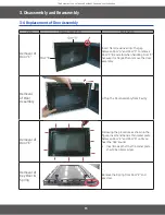
Page 15: ...emove Door C Be careful when handling Door C because it is fragile Then remove the door assembly Removal of Door Assembly Lift up the DoorAssembly from Cavity Removal of Door E Following the procedure as shown in the figure insert and bend a thin metal plate between Door E and Door A until you hear the tick sound Insertion depth of the thin metal plate should be 0 5mm or less Removal of Key Door S...

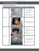
Page 16: ...e turn table motor cover from case bottom CAUTION Remove sharp edge after cover removal 3 Disconnect leads from motor 4 Remove the screws securing motorto bottom of over cavity Drive Motor 5 Lift out the motor 6 When replacing the motor be sure to remount it in the correct position NOTE The shaft of motor should fit tip coupler 7 When reassemble a drive motor cover give a turn in a 180 and fix wit...

Page 17: ...bly screw screw 1 Be sure to ground any static electric charge in your body and nevertouch the control circuit 2 Disconnect the connectors from the control circuit board 3 Remove screws securing the control box assembly Removal of Ass y P C B Assembly Assy Key Module Assy PCB Screw Screw 1 Remove screws securing the control circuit board 2 Lift up the control circuit board from the Ass y control b...

Page 18: ...3 7 Replacement of Grill heater Parts Explaination Photo Explaination Braket Upper 1 Remove 2 screw from the Bracket upper Spring Plate 2 Press the Center of spring plate and Slice with tools Grill Heater 3 Remove fan motor and then remove the Nuts for disassemble the Grill Heater and lead Wire ...

Page 19: ...authorization 4 Troubleshooting 4 Troubleshooting 4 1 Parts checking method Parts Photo Good No Good Fuse 0 1 1 Ω 100 MΩ exceed T C O 0 1 1 Ω 100 MΩ exceed H V Trans 1 9 Ω 100 MΩ exceed Fan Motor 10 99 Ω 100 MΩ exceed Grill Heater 10 99 Ω 100 MΩ exceed ...

Page 20: ...n and an oven CMO OTR Grill Convection Commercial etc 2 All sensors and devices have their own number ex Gas Easy PH Sensor 1 Temp Sensor 2 3 Of each device No 0 2 referto Check Option1 3 C 1 0 0 Others 0 Check option 1 1 Gas Easy PH Sensor 1 Check option 2 2 Temp Sensor 2 Check option 3 7 Steam Sensor A Function d Door Key F Master Slave Communication X additional Information code ...

Page 21: ...on 4 Troubleshooting 4 3 Information Code List Device Information Code Symptom Solution Page Door Key C d0 Key Short Information code 10 seconds If KEY input is successive more than 10 seconds marks C d0 and converts to cancel mode Turn off set and restart 22 page ...

Page 22: ...mation Code C d0 YES NO Perform the operation again and check if it is working properly S W Fault YES Is a specific key not recognized The membrane is defective Replace the Control Panel Is the key not recognized at all After Power On does the symptom continue Replace the PCB NO NO YES Is the key recognized intermittently NO YES Membrane ...

Page 23: ...to User Manual Menbrane type Tact type YES YES Buttons of the control panel do not work Inspection method Are button pressed in the correct order Is the connector of the control panel normal Replace PCB PCB Membrane Switch Connector Connector Connector Tact Switch PCB 4 4 2 If button malfunction ...

Page 24: ...h voltage ciruits on the previous page Door Open Door Closed Method to control latch switch YES Door Key 1 Loosenly tighten the nut to check whether the primary interlock switch works by slightly moving latches to right and left Then firmly tighten nuts 2 Loosenly tighten the nut to check whether the primary interlock switch works by slightly moving latches to right and left Then firmly tighten nuts...

Page 25: ...ll Heater Relay Grill Heater Control 5 RY05 T T Relay Turn Table Motor Control model option 6 CN01 Power Relay Connector A Terminal for Connecting with Power supply Relay Contact Load Control 7 CN02 Door switch Sensing Connector A Terminal for Connecting with Door Switch 8 CN03 Membrane switch Connector A Terminal for Connecting with Membrane Switch 9 CN04 T T Connector A Terminal for Connecting w...

Page 26: ...ER RELAY CONTACT2 HVT POWER2 CN03 1 KEY OUTPUT1 2 KEY OUTPUT2 3 KEY OUTPUT3 4 KEY OUTPUT4 5 KEY OUTPUT5 6 KEY OUTPUT6 7 KEY OUTPUT7 8 KEY OUTPUT8 9 KEY INPUT1 10 KEY INPUT2 11 KEY INPUT3 12 KEY INPUT4 13 KEY INPUT5 14 ENCODER COMMON ENCODER S W MODEL CN02 1 DOOR SWITCH 12V 2 GND 3 DOOR SWITCH RY_12V 4 GND CN02 1 MONTOR S W 2 NO PIN 3 AC POWER LIVE AC220V 240V 4 NO PIN 5 MAIN RELAY Connect with Lam...

Page 27: ... WHT BRN RED RED RED RED BRN BLU WHT BLK ORG ORG YEL BRN MAGNETRON HIGH VOLTAGE DIODE TO CHASSIS FA F HIGH VOLTAGE TRANSFORMER POWER RELAY DOOR SENSING SWITCH BOTTOM MONITOR SWITCH CENTER BRN BLU BLK BLU SECONDARY SWITCH TOP HIGH VOLTAGE CAPACITOR RED ORG WHT SYMBOL COLOR BLU BLK RED ORANGE WHITE BLUE BLACK ...

Page 28: ...28 This document can not be used without Samsung s authorization 6 Wiring Diagrams 6 1 Wiring Diagrams ...

Page 29: ...F C104 5V 4 3 1 2 5 6 8 9 10 PC817 PC101 EE1916 NERO ST101 1 2 3 4 C105 100nF C102 10uF 12V 5V 1N4148M D10 2K MTZJ4 3B ZD101 OR04 1K R105 100K R107 5V 10K R101 KRC246 TR08 R06 R102 4 7K 1nF 100 R03 C11 1 3 2 4 4 7K LF 2CTOP L101 BD101 DF06S SMW250 07AV_RED 1 3 5 7 D101 1N4007 5V CN01 TR05 KRA226 D04 MM4148 KRC246 TR03 10K R20 5V 1nF KRA225M TR101 C12 47K R13 R01 BZ01 CBE2220BA 20K 1N4148M D11 TNY2...

Page 30: ...d under applicable International and or domestic law Samsung Electronics Co Ltd 2018 Printed in Korea GSPN GLOBAL SERVICE PARTNER NETWORK Area Web Site Europe CIS Mideast Africa gspn1 samsungcsportal com Asia gspn2 samsungcsportal com North Latin America gspn3 samsungcsportal com China china samsungportal com ...

Reviews: