E-
18
I
NSTALLING THE
I
NDOOR
U
NIT
F1 F2 V1 V2
1(L) 2(L)
F
1
(F
3
) F
2
(F
4
)
V
1
V
2
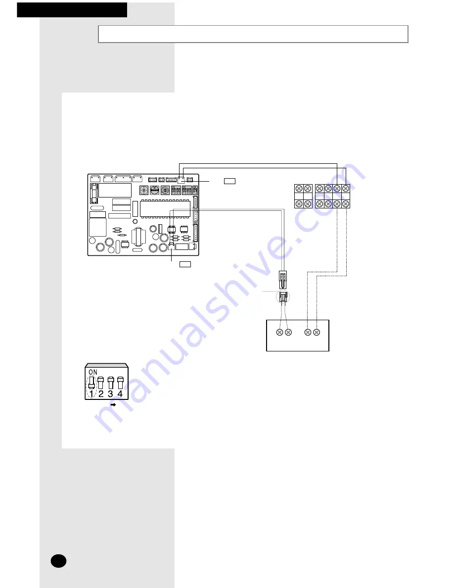
Indoor Unit
Terminal Block
Wired Remote
Controller (Optional)
Change DIP switch
in the indoor unit PCB
Accessory in the remote controller
➢
Dashed lines(cables) are not supplied as accessories.
K1 K2 K3 K4
Indoor Unit PCB
Connect the power cable, which is connected with the outdoor unit and supplied by another source,
making sure that the power cable terminal should not be changed.
The F3 and F4 communication cable may be cross-connected, however, it is recommended that they are
connected to the corresponding F3 and F4 terminal.
K1 : ON OFF
Wiring Wired Remote Controller (Optional)
CN32 BLU
CN43 WHT

