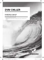
background image

DB68-06087A-00

@FCU AIM-F10N_IM_06087A-00_EN_160307.indd   2

2016-03-15   오후 5:11:53

Summary of Contents for MIM-F10N

Page 1: ...DB68 06087A 00 FCU AIM F10N_IM_06087A 00_EN_160307 indd 2 2016 03 15 오후 5 11 53 ...

Page 2: ...rface Module MIM F10N Thank you for purchasing this Samsung Product Before operating this unit please read this Insatallation manual carefully and retain it for future reference FCU AIM F10N_IM_06087A 00_EN_160307 indd 3 2016 03 15 오후 5 11 53 ...

Page 3: ...alfunction water leakage electric shock or fire Make sure to use the supplied cables y y If not there is risk of fire or damage to the product Make sure that all wiring work is done by qualified person complying regional standards and instructions in this manual y y If the installation is done by unqualified person there is risk of product malfunction electric shock or fire caused by incorrect ins...

Page 4: ...of electric shock or abnormal operation For operation WARNING Do not attempt to repair disassemble or modify the product yourself y y There is potential risk of product damage electric shock or fire When repair is needed consult qualified installer or service center Contact the service center when you need to dispose the product Do not attempt to move or re install the product that is already inst...

Page 5: ...e and FCU KIT 1 Fix the FCU interface module case at fixing point of FCU KIT by 1 screw 2 Attach FCU interface module to the case and connect power and communication cable y y If you use upper level controller such as DMS OnOff controller etc with the FCU interface module installed use of centralized control 02 series installation option SEG5 must be set as Enable INSTALLATION FCU AIM F10N_IM_0608...

Page 6: ...pper level controller 12V F1 F2 FCU KIT CAUTION You should separate power cable and communication cable of FCU KIT Abnormal operation of the product may occur due to the electric problem FCU interface module AIM F10N supports connection between NASA communication upper level controller NASA communication FCU KIT It does not support Non NASA communication upper level controller NASA communication F...

Page 7: ...controller and the farthest FCU interface module should be within 1000 m You should switch off the power supply before installation The wiring should be installed in accordance with electric wiring regulations and should be placed inside the wall so that users cannot touch them Setting option switch and address switch CN4 CN3 RED CN2 BLK YEL RED Y GRN Address switch for FCU interface module 1 Swit...

Page 8: ...odule is assigned by address switch of the FCU interface module NOTE The default setting of option switch is OFF for both SW4 and SW5 When installing 16 FCU KITs CN4 CN3 RED CN2 BLK YEL RED Y GRN DMS FCU interface module R1 R2 F1 F2 FCU KIT FCU KIT FCU KIT FCU KIT FCU KIT NOTE FCU interface module can be applied from DMS2 5 or later version Refer to FCU KIT installation manual for wiring work of F...

Page 9: ...e is detected as valid communication RED LED will blink NOTE YEL LED is not in use 7 SEGMENT indication 1 When initializing power supply program code will be indicated y y Exmaple of program code 17 89 A3 16 2 Then tracking of FCU KIT will be on progress and will be indicated 3 After tracking is done communicating address of FCU KIT will be indicated in order when the communication is normal 4 Whe...

Page 10: ...terface module y y If SW4 1 is OFF reset the power of FCU interface module to reset the automatic address 8 When more than 16 FCU KITs are installed will be indicated alternatively y y Install the FCU KIT less than 16 and reset the power of FCU interface module 9 When indoor units and FCU KITs are installed together will be indicated alternatively y y Indoor units and FCU KITs cannot be installed ...

Page 11: ...10 INSTALLATION Memo FCU AIM F10N_IM_06087A 00_EN_160307 indd 10 2016 03 15 오후 5 11 54 ...

Page 12: ...11 INSTALLATION FCU AIM F10N_IM_06087A 00_EN_160307 indd 11 2016 03 15 오후 5 11 54 ...

Reviews: