


6
INS
TALLA
TION
• You should be aware that power may not be supplied to FCU KIT and interface module
if power polarity of V1 and V2 is connected opposite.
• Terminal block of upper level controller connection on FCU interface module has to be
tightened by M3 size screw, and the torque is 0.5 ~ 0.75 N.m.
3
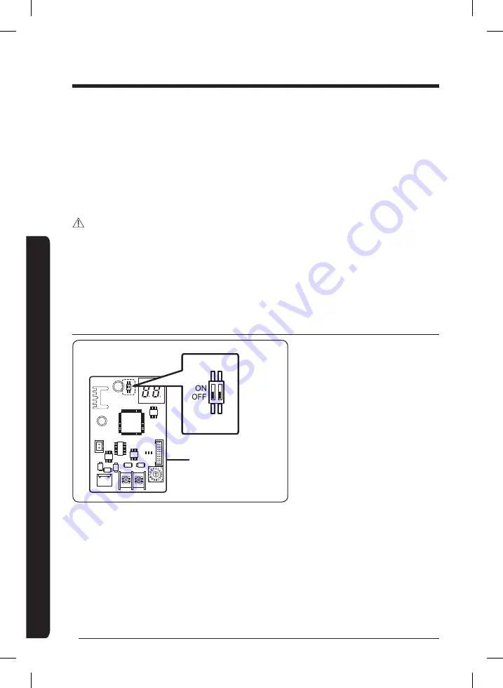
Set the address of FCU interface module.
y
y
The address of each FCU interface module should be set differently.
CAUTION
• The cable length between the upper controller and the farthest FCU interface module
should be within 1000 m.
• You should switch off the power supply before installation.
• The wiring should be installed in accordance with electric wiring regulations and should
be placed inside the wall so that users cannot touch them.
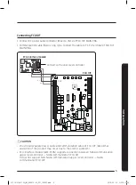
Setting option switch and address switch
CN4
CN3
RED
CN2
BLK
YE
L
RE
D
Y-
GRN
Address switch for
FCU interface module
1
Switch for setting address: Address switch, set the address within 0 ~ F (0 ~ 15)
(Address between each FCU interface module should be set differently.)
2
Option switch
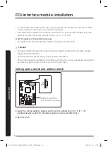
FCU interface module installation
@FCU AIM-F10N_IM_06087A-00_EN_160307.indd 6
2016-03-15 오후 5:11:54


