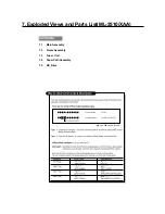
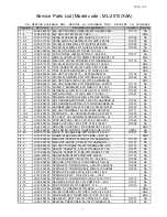
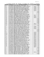
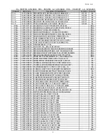
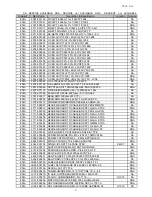
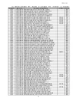
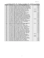
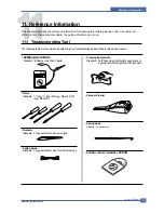
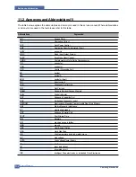
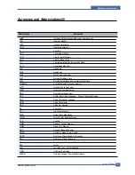
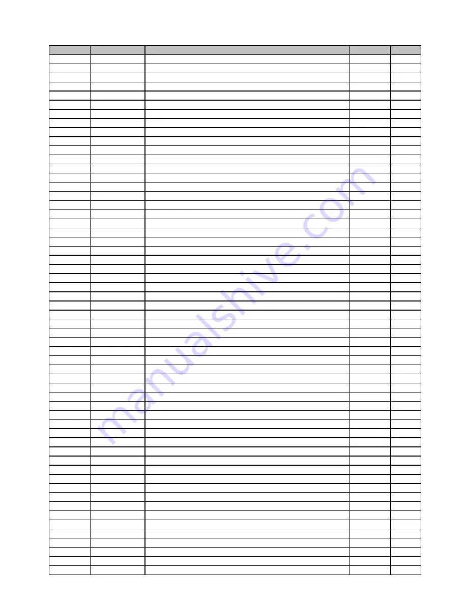
background image

Parts List

Drawer#

SEC-Code

Description & Specification 

Location

Service

SA : SERVICE  AVAILABLE   SNA   : SERVICE   not   AVAILABLE    DNA  :   DELIVERY    not   AVAILABLE 

#N/A

JC39-00482A CBF HARNESS-MICRO SW;ML-2010,WIRE HARNES

O1023

SA

#N/A

JC41-00350A PCB-MAIN;ML-2510,FR-4,2L,V0.3,1.6T,94.25

SNA

#N/A

JC46-00291A S/W APPLICATION-CD;-,ML-2510,PRT DRV,1.0

SNA

#N/A

JC61-00025A SPRING ETC-CS-CHARGE APOLLO;SF-5100,SUS

SNA

#N/A

JC61-00047A SPRING ETC-TR L HAWK;ML-6060A,SWP-B,-,-,

O1030

SA

#N/A

JC61-00049A SPRING ETC-TR(KOR);ML-4500,SUS304-WPB,0.

SNA

#N/A

JC61-00056A SPRING ETC-PR(7300);ML-7300,PIANO WIRE,1

O1031

SA

#N/A

JC61-00060A SPRING ETC-TS BLADE;ML-6060,SUS304 WPB,0

SNA

#N/A

JC61-01150A FRAME-M_LSU;ML-1610,PC+GF 20%,-,-,BLK,-,

SNA

#N/A

JC61-01163A FRAME-M-DEVE LOWER;ML-1610,ABS,-,HB,BLK,

SNA

#N/A

JC61-01165A BRACKET-P-CLEANING;ML-1610,SECC,1.2T,-,2

SNA

#N/A

JC61-01166A BRACKET-P-SUS BLADE;ML-1610,SPCC+NI,1.2T

SNA

#N/A

JC61-01167A PLATE-M-DEVE_L;ML-1610,PC,2,62.4,88,BLK,

SNA

#N/A

JC61-01168A PLATE-M-DEVE_R;ML-1610,ABS,2,62.4,87.7,B

SNA

#N/A

JC61-01184A FRAME-M_WTB INITIAL;SCX-4521F,ABS+GF20,-

SNA

#N/A

JC61-01263C PLATE-MP;ML-2571N,HIPS,2.5,278.2,123,V.W

O1040

SA

#N/A

JC61-01281A BRACKET-P-BAR_PICK_UP;ML-1610,SECC,T1.0,

SNA

#N/A

JC61-01442A PLATE-LSU_SLIT_B;SCX-6345N/XRX,STSC 301,

SNA

#N/A

JC61-01464A BLADE-P_SUS;ML-2010,SUS301-CSP 1/2H T0.0

SNA

#N/A

JC61-01709A PLATE-KNOCK_UP;ML-2571N,PC/ABS,T2.5,W82.

O1041

SA

#N/A

JC61-01713A STOPPER-PICK_UP R;ML-2571N,POM,-,D17,L20

O1044

SA

#N/A

JC61-01714A STOPPER-PICK_UP L;ML-2571N,POM,-,D17,L20

O1045

SA

#N/A

JC61-01715A PLATE-P_IDLE HOLDER;ML-2571N,SECC,T1,-,2

O1046

SA

#N/A

JC61-01718A HOLDER-IDLE ROLLER;ML-2571N,POM,-,26,12.

O1049

SA

#N/A

JC61-01719A HOLDER-EXIT R;ML-2571N,PC,1.5,10,21,BLAC

O1050

SA

#N/A

JC61-01747A HOLDER-SPRING;ML-2571N,PET+GF30%,1.5,11.

O1052

SA

#N/A

JC62-00145A SEAL-SUPPLY;ML-1610,CHLOROPRENE RUBBER

SNA

#N/A

JC62-00146A SEAL-SUPPORT L;ML-1610,MICRO URETHANE,-,

SNA

#N/A

JC62-00147A SEAL-SUPPORT R;ML-1610,MICRO POLYURETHAN

SNA

#N/A

JC62-00148A SEAL-CAP SIDE;ML-1610,POLYURETHANE FOAM,

SNA

#N/A

JC62-00149A SEAL-CAP DEVE;ML-1610,POLYURETHANE FOAM,

SNA

#N/A

JC62-00150A SEAL-SUS BLADE;ML-1610,POLYURETHANE FOAM

SNA

#N/A

JC62-00151A SEAL-DEVE L;ML-1610,PTFE FELT+MICRO URET

SNA

#N/A

JC62-00153A SEAL-BRKT CLEANING;ML-1610,POLYURETHANE

SNA

#N/A

JC62-00154A SEAL-OPC CLEAN_L;ML-1610,PTFE FELT+URETH

SNA

#N/A

JC62-00155A SEAL-OPC CLEAN_R;ML-1610,PTFE FELT+URETH

SNA

#N/A

JC62-00156A SEAL-BOSS_R;ML-1610,CR,BLACK,T5,-,D7.5,-

SNA

#N/A

JC62-00165A SEAL-FILM REAR;ML-1610,PET,-,T0.075,9,22

SNA

#N/A

JC62-00310A SEAL-LSU;ML-2570,EPDM,2,168.3,115

SNA

#N/A

JC63-00290A SHEET-HOLDER PAD;ML-1750,PC,0.125T,50,18

O1055

SA

#N/A

JC63-00614A COVER-M_LSU;ML-1610,ABS,T1.5,W171.3,L116

SNA

#N/A

JC63-00628D TRAY-EXTENSION_L;ML-2571N,HIPS,2.5,80,11

SNA

#N/A

JC63-00711A SHEET-MP;SCX-4521F,PET,T0.188,215.0,60.8

O1057

SA

#N/A

JC63-01106B COVER-SIDE L;ML-2570,HIPS,2,288,239,-,SE

SA

#N/A

JC63-01108C COVER-TOP;ML-2510,HIPS,2,248,245,HB,-,-,

SNA

#N/A

JC63-01119A COVER-M_PAPER;ML-2571N,ABS,2.5,270,138,H

O1064

SA

#N/A

JC63-01151A SHEET-NETWORK;ML-257O,PC,0.254,18,15,-,-

SA

#N/A

JC64-00185A HANDLE-M-DEVE;ML-1610,HIPS,T1.5,110,125.

SNA

#N/A

JC65-00011A TERMINAL-DEVE KEY;SCX-4521F,STS304WPB,-,

SNA

#N/A

JC66-00012A GEAR-OPC R;SF-5100,POM(M90-44),BLK,M0.6,

O1065

SA

#N/A

JC66-00529A ROLLER-M-IDLE FEED;ML-1510,POM(DELRIN890

O1066

SA

#N/A

JC66-00720A SHAFT-P-CORE;ML-1750,SECC 1.2T,203,-,-,-

O1068

SA

#N/A

JC66-00817A GEAR-AGITATOR;ML-1610,POM,0.6,24,-,NTR,2

SNA

#N/A

JC66-00818A GEAR-RDCN;ML-1610,POM,0.8/0.6,-,-,NTR,-,

SNA

#N/A

JC66-00819A GEAR-SUPPLY;ML-1610,POM,0.6/0.6,20/19,-,

SNA

#N/A

JC66-00820A GEAR-DEVE;ML-1610,POLYKETONE,0.8,14,-,NT

SNA

#N/A

JC66-00821A GEAR-OPC_L;ML-1610,PC+PTFE,0.8,30,-,BLK,

SNA

5

Summary of Contents for ML-2510 series

Page 1: ...pe Cassette Emulation SPL ML 2510 PCL ML 2570 ML 2571N Processor 150MHz Jupiter4e CPU 400MHz SPGP V3 CPU Memory ML 2510 SDRAM 8MB ML 2570 2571N SDRAM 32MB MP Cassette 250 pages Face Down 100 pages Fuser Design Lamp Type I O ML 2510 USB1 1 IEEE 1284 ML 2570 2571N USB2 0 IEEE 1284 Machine Life 50K pages Basic Model ML 2571N Manual SERVICE ...

Page 2: ...rison Table 2 5 2 4 ACCESSORY 2 5 3 System Overview 3 1 System Outline 3 1 3 2 H W Structure and Descriptions 3 7 3 3 S W Structure and Descriptions 3 23 3 4 Initial Product Installation 3 27 4 Alignment and Adjustments 4 1 Sample Pattern 4 1 4 2 Control Panel 4 2 4 3 Consumables and Replacement Parts 4 4 4 4 Periodic Defective Image 4 5 4 5 How to use DCU 4 6 4 6 Paper Path 4 11 ...

Page 3: ...6 17 7 Exploded Views Parts List 7 1 Exploded Views and Parts List 7 1 8 Block diagram 8 1 ML 2510 H W Block Diagram 8 1 8 2 ML 2570 2571N H W Block Diagram 8 2 9 Connection Diagram 9 1 ML 2510 Connection Diagram 9 1 9 2 ML 2570 2571N Connection Diagram 9 2 10 Schematic Diagram 10 1 PCL_Main Board 10 1 10 2 GDI_Main Board 10 6 10 3 Connector Circuit Diagram 10 17 10 4 SMPS Circuit Diagram 10 18 10...

Page 4: ...e Information 11 1 Troubleshooting Tools 11 1 11 2 Acronyms and Abbreviations 11 2 11 3 Selecting printer locations 11 4 11 4 Sample Tests Patterns 11 5 12 Circuit Description 12 1 Engine Controller 12 1 Continued ...

Page 5: ... electric shock or fire may occur 3 Laser Safety Statement The Printer is certified in the U S to conform to the requirements of DHHS 21 CFR chapter 1 Subchapter J for Class 1 1 laser products and elsewhere is certified as a Class I laser product conforming to the requirements of IEC 825 Class I laser products are not considered to be hazardous The laser system and printer are designed so there is...

Page 6: ...d place other materials on it Do not fix with sta ples If the power cord gets damaged a fire or electric shock can happen A damaged power cord must be replaced immediately Do not repair the damaged part and reuse it A repaired part with plastic tape can be cause a fire or electric shock Do not spread chemicals on the power cord Do not spread insecticide on the power cord A fire or electric shock c...

Page 7: ...t near to heater A fire can be occurred 1 2 4 Assembly Disassembly precaution When replacing parts do it very carefully Memorize the location of each cable before replace parts for recon necting it afterwards Memorize Please perform the steps below before replace or disassembly the parts 1 Check the contents stored in the memory All the information will be erased after replacing main board The inf...

Page 8: ...am to prevent electrostatic charge buildup in the vicinity of the assembly 3 Use only a grounded tip soldering iron to solder or desolder ESDs 4 Use only an anti static solder removal device Some solder removal devices not classified as anti static can generate electrical charges sufficient to damage ESDs 5 Do not use Freon propelled chemicals When sprayed these can generate electrical charges suf...

Page 9: ...cations Item Descriptions Print Method Electro photographic Printing Developing system Non Magnetic Mono Component Developing System Print Speed 24 PPM A4 size 25 PPM Letter size Resolution True 1200 X 600 DPI 1200 X 1200 ML 2570 2571N Source of Light Laser diode LSU Laser Scanning Unit Warm Up Time Cold Warm up 15sec Sleep mode 15sec First Print Time Less than 9 seconds Ready to 1st page out Feed...

Page 10: ...GP V3 400MHz Memory Standard Max 8MB Max 8MB ML 2510 32MB Max 32MB ML 2570 2571N Type SDRAM Expand Memory Slot Type NO Compression Technology MET Memory Enhancement Technology Emulation Standard SPL PCL Auto Emulation Sensing YES Interface USB 1 1 Compatible with USB 2 0 IEEE 1284 for ML 2510 USB 2 0 IEEE 1284 for ML 2570 2571N Option NO Auto Interface Sensing YES Font Type Windows Fonts Number NO...

Page 11: ...del 70W Ave or less ML 2570 2571N Model Power Save 6 5W Ave or less ML 2510 Model 8 5W Ave or less ML 2570 2571N Model 2 2 4 Environmental Range Item Operating Storage Temperature 10 30 oC 50 90 oF 20 40 oC 4 104 oF Humidity 20 80 RH 10 80 RH 2 2 5 Toner Cartridge Item Descriptions Remark Life span Starter 1 000 Pages initial A4 Size ISO 19752 Pattern Running 3 000 Pages sailes Standard Coverage S...

Page 12: ... X 279 8 5 X 11 O US Folio Legal13 216 X 330 8 5 X 13 O Legal Legal14 216 X 356 8 5 X14 O Executive 184 X 267 7 25 X10 5 O Statement 140 X 216 5 5 x8 5 O ISO B5 176 X 250 O JIS B5 182 X257 O A5 148 X 210 O A6 105 X148 O No 10 Env 105 X 241 4 15 X 9 5 O Monarch Env 98 X191 3 87 X 7 5 O DL Env 110 X 220 4 33 X 8 66 O C5 Env 162 X 229 6 38 X 9 01 O C6 Env 114 X 162 4 49 X 6 38 O Transparency OHP A4 o...

Page 13: ...Plain paper 16 to 24 lb Bond 60 to 90g m2 16 to 24 lb Bond 60 to 90g m2 16 to 24 lb Bond 60 to 90g m2 Thick stock 24 90 lb Index 163g m2 24 90 lb Index 163g m2 24 90 lb Index 163g m2 Physical Type Laser Printer with Internal Controller Laser Printer with Internal Controller Laser Printer with Internal Controller Dimensions w output 352mm x 298mm x 243mm 352mm x 298mm x 243mm 352mm x 298mm x 243mm ...

Page 14: ...e Quantity INA ACCESSORY JC99 01993J S W APPLICATION CD JC46 00287A 1 COVER M_PAPER PAPER COVER JC63 01119A 1 MANUAL CARD WARRANTY CARD JC68 00690A 1 Acessory Code Quantity INA ACCESSORY JC99 01986C S W APPLICATION CD JC46 00291A 1 COVER M_PAPER PAPER COVER JC63 01119A 1 MANUAL CARD WARRANTY CARD JC68 00690A 1 ...

Page 15: ...System Overview Samsung Electronics Service Manual 3 1 3 3 3 System Overview 3 1 System Outline Paper Path Layout 12 14 13 BIN PATH MAIN PBA SMPS HVPS 13 12 14 ...

Page 16: ...Samsung Electronics Service Manual System Overview 3 2 Unit Layout HVPS SMPS Main PBA Motor LSU Panel ...

Page 17: ...aring from Main Motor 8 Pick_up Roller Driver Solenoid 9 Paper detecting Sensor Photo Sensor 10 Paper Size Sensor None 11 Paper Exit Type Face Down 3 1 2 Transfer Ass y The transfer roller delivers the toner of the OPC drum to the paper The life span Print over 50 000 sheets in 16 30 3 1 3 Driver Ass y It is a power delivery unit by gearing By driving the motor it supplies the power to the feeding...

Page 18: ...less Overheat 210 or less 4 Heat roller Length 254 mm Valid length 222 mm GND Type H R Bearing Grounding type By SECC Fuser frame 5 Pressure roller Shaft Length 239 5 mm Rubber Length 222 mm 6 Paper separation method Teflon Coating with mold Claw System 7 Safety Relevant Facts Protecting device when overheating 1st protecting device H W cuts off when detecting an overheating 2st protecting device ...

Page 19: ...tes as the same speed as the paper feeding speed It creates the HSYNC signal and sends it to the engine when the laser beam of the LSU reaches the end of the polygon mirror and the engine detects the HSYNC signal to arrange the vertical line of the image on the paper After detecting the HSYNC signal the image data is sent to the LSU to arrange the its margin on the paper The one side of the polygo...

Page 20: ...ade Developing Method Non magnetic 1 element contacting method Toner Non magnetic 1 element shatter type toner The life span of toner 3 000 sheets ISO 19752 Pattern A4 standard Toner Cartridge Initial 1 000 Sales 2 000 Toner remaining amount detecting sensor None OPC Cleaning Collect the toner by using electric static FILM OPC Management of disusable toner Collect the toner by using electric stati...

Page 21: ...d IEEE 1284 Parallel Interface capacity 3 2 1 1 Main Control ML 2510 2570 2571N of Main Control are composed of CPU and Print and operate follows function by CPU Bus Control I o Handling each Driver and PC Interface Main Control operate its full function on the Main B d and CPU control Controller ASIC 3 2 1 2 CPU ML 2510 Use 32Bit RISC Processor of Jupiter4e which is built in Memory while ML 2570 ...

Page 22: ... capa 8M Byte basic for ML 2510 8M Printing System Working Memory Area 32M capa 32M Byte basic for ML 2570 2571N 32M Printing System Working Memory Area Access Time 60 nsec 3 2 1 5 ENGINE This recording method is electrophography method using LSU which toner is composed of 1 component and non magnetic 1 Recording Method LSU Laser Scanning Unit 2 Printing Speed 24ppm In continuing printing base A4 ...

Page 23: ...in Board are composed of Engine and Controller on the one Board Main Board control to send Current Imagedml Video Data to LSU to print and have motor Driving and Circuit for the current driving and also include Paper Exit Sensor Cover Open s w panel s w ML 2510 ML 2570 2571N ...

Page 24: ...core voltage to CPU by converting 3 3V to 1 8V for ML 2510 EEPROM U8 93C66 for ML 2510 24C32 for ML 2570 2571N It is an EEPROM with 12C method SMPS connector CN8 It connects SMPS supplies the power and delivers the high voltage contol signal etc If a harness is not normally connected to this connector power cannot be supplied LSU connector CN12 It connects a LSU DC Motor connector CN11 It connects...

Page 25: ... Data cache Single memory bus architecture 3 Built in Flash Memory 4MBits 128Kx32bits Serial programming mode using flash programmer tool Internally flash memory read write operation support Programmable access timing control 4 32MB Special function Register Area 5 Directly connected to 3 external IO banks IOC 32 MB size in each IO bank Programmable setup access hold timing Programmable recovery t...

Page 26: ...ntrol for Laser Diode with PID control method using internal 10 bits DAC LSU clock generation Brushless DC motor control clock generation 13 ADC Interface 4 channels ADC interface for analog devices such as temperature sensor Programmable ADC Clock Cycle Automatic or Manual AD Conversion support 4 Special Function Registers for monitoring the ADC results for 4 channels 14 PWM Controller 4 PWM outp...

Page 27: ...DQM1 0 BA1 0 SCKE ADDR18 0 DATA15 0 nOE ADDR DATA BUS MUX IOC 3 CH ROMC 1 CH nIOCS1 0 INTC TCU MISC PLL pll 2096x pll 2073x CLOCK RESET EXTCLK nRESET OM2 0 CAP2 0 MOTORC MOTPAT5 0 LSUC dac1264x_1455 nLREADY nHSYNC VDO ADC INTERFACE adc1275x_pc ADCIN3 0 PWM PWM3 0 LSUCLK SCLK A H B A P B A H B UART RXD1 0 TXD1 0 SHPERIOD nLDON DACOUT TEST XI XO USB CORE USB1 1 D D Dpullup VBUS nSTROBE nINIT nSLCTIN...

Page 28: ... Auto Boot Mode Using Internal SRAM 4KB MAC 10M 100Mbps Full IEEE 802 3 Compatibility Engine Controller LSU Interface Unit Step Motor 2 Channels PWM 8 Channels ADC 6 Channels I2C Controller I2C S BUS Slave Device Support I2C Version 2 1 RTC RTC Core Voltage 3V PLL 3 PLL MAIN PCI PVC 3 2 3 4 Memory Flash Memory It stores System Program and downloads the System Program through PC Interface and in ca...

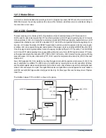
Page 29: ...System Overview Samsung Electronics Service Manual 3 15 3 2 3 5 SPGPv3 Internal Block Diagram ...

Page 30: ...nd downloads system program through the PC Interface Capacity 8M Byte NOR Flash Random Access Time 10 us Max Serial Page Access Time 50ns Min 3 2 3 7 SDRAM It is used as swath buffer system working memory area etc while Printing Capacity The 32M Byte is for this model 32M Printing System Working Memory Area ...

Page 31: ... paper empty is detected by the empty sensor mounted to an engine board and the actuator mounted to a frame Paper senses the on off time of the empty sensor by using CPU and informs the normal operation status and the jam occurrence status to CPU 3 2 4 3 Jam Cover Cover Open Sensing ML 1610 uses two M S one senses the cover open and the other senses the jam cover open The cover open sensor is loca...

Page 32: ...tputs the 5V 24V to supply the power to the main board and other board It is consisted of the AMPS part which supplies the DC power for driving the system and the AC heater control part which supplies the power to fuser SMPS has two output channels Which are 5V and 24V Pin Signal Pin No Pin Name 1 24VS2 2 24V 3 24VS1 4 24VS1 5 5V 6 DGND 7 DGND 8 P_REGI 9 FUSER ON CON2 ...

Page 33: ...problem within 1 min at 1000Vac 10mA Leaking Current under 3 5mA Running Current under 40A PEAK AT 25 COLD START under 50A PEAK In other conditions Rising Time within 2Sec Falling Time over 20ms Surge Ring Wave 6KV 500A Normal Common No Items CH1 CH2 Remarks 1 Channel 5V 24 0V 2 Connector pin CON 3 CON 3 5V PIN 11 12 24V PIN 2 3 4 GND PIN 8 9 GND PIN 6 7 3 Rated Output 5V 5 24V 5 4 75 5 25V 20 4 2...

Page 34: ...Trigger 6 5 Input Voltage Variation 5 below Variation 21 6V 26 4V Load Variation below Out Voltage Rising Time 100 ms Max Out Voltage Falling Time 100 ms Max Transfer Variation Voltage on Environment Variation 650 V Duty 10 5KV Duty 90 Control Method on environment THV PWM ACTIVE transfer Active signal of environment sensing voltage is input and get feed back current and recalculate it to resisten...

Page 35: ...WM the CPU output is HV output when PWM is low 4 Supply Output Voltage 550 V 8 6 ZENER using DEV Input contrast of the output stability degree under 5 Loading contrast 5 or less Output Voltage Rising Time 50 ms Max Output Voltage Falling Time 50 ms Max Output Loading range 10 1000 Output Control Signal BIAS PWM the CPU is HV output when PWM is low Input ...

Page 36: ...art When the HEATER ON signal is turned on at engine the LED of PC1 Photo Triac takes the voltage and flashes From the flashing light the Triac part light receiving part takes the voltage and the voltage is supplied to the gate of Triac and flows into the Triac As a result the AC current flows in the heat lamp and heat is occurred On the other hand when the signal is off the PC1 is off the voltage...

Page 37: ...nd is detected this firmware controls the Engine Mechanism according to the printing process and paper feeding state And with the Sleep command or Wake Up command this firmware controls the Engine state 3 3 2 Engine Control F W Overview Engine Control F W is executed every 10msec by timer interrupt of main system And it consists of 3 control modules Engine Main Control Interface Control and Sensin...

Page 38: ...re of Engine Control F W Main F W of the printer controller Device Units Fixing Unit LSU HVPS Fan Unit Motors Solenold Clutch Power On Initial Interface Control Module Engine Main Control Module Sensing Unit Control Module Hardware Devices Mechanical Device Engine F W ...

Page 39: ...n error occurrs Lsu Error When the error occurrs it does not indicate an error It accomplishes printing only again If even time when it judges an error it informs an error Concretely speaking if the LReady or Hsync error happens the paper exits out beforehand And then the engine mode is changed to recovery mode and the engine informs the main system of the engine mode And the engine checks the LSU...

Page 40: ...verview 3 26 START Global Timer Increment Get A DC Value Tempe rature Control the fixing unit Check error condition for the fixing unit Control the fan unit Get status value of each sensor Set present status flag of each sensor F W Architecture ...

Page 41: ...al Product Installation 3 4 1 Accessory List Remove the printer and all accessories from the packing carton Make sure that the printer has been packed with the following items 3 4 2 Installing the Toner Cartridge 1 Grasp the front cover and pull it toward you to open ...

Page 42: ... 28 2 Remove the toner cartridge from its bag and remove the paper covering the cartridge 3 Gently shake the cartridge from side to side to distribute the toner evenly inside the cartridge 4 Locate the cartridge slots inside the printer one on each side ...

Page 43: ...9 5 Unfold the toner cartridge handle and grasp it Insert the cartridge in the printer until it snaps into place 6 Close the front cover Make sure that the cover is securely closed If the cover is not firmly closed printing errors may occur when you print ...

Page 44: ...y 1 Grasp the paper input tray and pull it toward you to open Pinch the rear guide and pull it out to extend the tray 2 Prepare a stack of paper for loading by flexing or fanning them back and forth Straighten the edges on a level surface 3 Load paper with the print side facing up Make sure that all four corners are flat in the tray ...

Page 45: ... the left flush against the paper 3 4 4 Connecting a Printer Cable To print from your computer you need to connect your printer to your computer with a Universal Serial Bus USB cable 1 Make sure that both the printer and the computer are turned off 2 Plug the USB printer cable into the connector on the back of the printer 3 Connect the other end of the cable to the USB port on your computer See yo...

Page 46: ... Serial Bus USB cable 2 Plug the other end into a properly grounded AC outlet and turn on the printer using the power switch 3 4 6 Printing a Demo Page Print a demo page to make sure that the printer is operating correctly 1 Press and hold down the Cancel button on the control panel for about 2 seconds to print a demo page 2 The Demo page shows the printer s current configuration ...

Page 47: ...atus Monitor allows you to see the printing status of the printer For details see Software User Guide 2 If you are printing in Linux Go to Software User Guide for information about installing the Linux driver 3 System Requirements Your machine supports following operating system Windows 98 Me 2000 XP The following table shows Windows requirements Item Requirements Operating System Window 98 Me 200...

Page 48: ...al sample patterns for maintenance With the sample patterns check the existence of the abnormality The patterns help to regularly maintain the product 4 1 1 Printing a Demo Page Print a demo page or a configuration sheet to make sure that the printer is operating correctly 1 Hold down the Cancel button for about 2 seconds to print a demo page ...

Page 49: ...Samsung Electronics Service Manual Alignment and Adjustments 4 2 2 The Demo page or the configuration sheet shows the printer s current configuration ...

Page 50: ...s button each time you load a sheet of paper in the tray when you select Manual Feed for Source from your software application Canceling print job Press this button during printing The On Line Error LED blinks while the print job is cleared from both the printer and the computer and then return to Ready mode This may take some time depending on the size of the print job In Manual Feed mode you can...

Page 51: ...s Toner Cartridge 3 000 Pages Sales 1 000 Pages Initial 4 3 Consumables and Replacement Parts The cycle period outlined below is a general guideline for maintenance The example list is for an average usage of 50 transmitted and received documents per day Environmental conditions and actual use will vary these factors The cycle period given below is for reference only ...

Page 52: ...ue to delinquent or damaged roller Refer to the table in below and check the condition of the roller No Roller Defective image Typical defect 1 OPC Drum 75 5mm white spot on black image or black spot 2 Charge Roller 37 7mm black spot 3 Supply Roller 47 5mm light or dark horizontal image band 4 Developing Roller 35 2mm horizontal image band 5 Transfer Roller 46 2mm image ghost 6 Heat Roller 77 7mm ...

Page 53: ... 01 02 03 04 20 30 40 50 69 60 62 68 64 70 71 72 73 95 MAIN MOTOR OPERATING SYSTEM MAIN HIGH VOLTAGE ON TRNSFER HIGH VOLTAGE ON THV REFERANCE VOLTAGE DEV SUPPLY HIGH VOLTAGE ON PTL ON LSU OPERATING SYSTEM PICKUP CLUTCH ON PEEMPTY PWITH NEW CRU TEST FEED EXIT SENSOR TEST COVER OPEN SENSOR TEST FUSER TEST HOT BURN TEST CLEAN MODE PRINT THV TRIGGER ALL HV FAN ON THV REFERENCE ON ERROR STATUS CODE STA...

Page 54: ...of the Feed Sensor 40 Feed Sensor off The paper has passed out of the Feed Sensor 50 Paper Out The paper has passed out of Exit Sensor 69 Sleep Mode The fuser power turned off to minimize the power consumption Code State Description 60 62 68 Fuser Error The error in the fuser occurred There is a short circuit in the thermistor and the thermostat while printing Low Temperature Error occurs 60 Open ...

Page 55: ...n High voltage probe should be used 02 Transfer High Voltage On THV 1000 voltage output by MHV terminal Caution High voltage probe should be used 03 Transfer High Voltage Reference on THV 1300 voltage output by MHV terminal Caution High voltage probe should be used 04 DEV supply High Voltage DEV Supply High Voltage Test The left one of the three LEDs in the self test panel is on when DEV high volt...

Page 56: ...the fuser is up to Printing Mode If you press the button once more the left LED is on and temperature of the fuser is up to overheat Mode 11 Hot Burn Test If the enter button pressed the printer is continuously printing without detection Turn the power off to stop operation 12 Cleaning Mode Print Mode Print the paper to clean the OPC Drum in the Cartridge 13 THV TRIGGER ALL HV All high voltage out...

Page 57: ...t Burn On 12 Clean Print Clean Printing 13 Thv Reference low adequate high 14 PTL PTL On PTL Off PTL No 15 FAN Fan On Fan Off 16 PickUp Manual Pickup On Manual Pickup Off 17 Manual Manual Sensor Manual Sensor Function 4 5 4 Self Test Button If the Self Test button pressed vertical lines are printed Turn the power on while pressing this button 89 shows in the DCU and the printer is warming up After...

Page 58: ...nsor via printing process Jam 1 occurs if the sensor is not operated after certain time passes 4 The paper passed the paper exit sensor moves out from the set Jam 2 occurs sometime after if the tailing edge of the paper is not coming out from the set after the leading edge of paper passes the paper exit sensor 8 9 10 11 BIN PATH 1 4 7 10 SMPS LSU Pick Up Roller Ass y Holder PAD SMPS 2 5 8 11 Fuser...

Page 59: ...erneath the inner cover It is hot and could cause burns The top and inner cover themselves may also be hot due to the heat roller Allows the printer to cool before opening the covers 4 6 1 Clearing Paper Jams Occasionally paper can be jammed during a print job Some of causes include The tray is overfilled The front cover has been opened during a print job Paper that does not meet paper specificati...

Page 60: ...justments Samsung Electronics Service Manual 4 13 4 Loosen the jammed paper if it is caught in the heat roller Then gently pull the jammed paper out 5 Close the inner cover and top cover Printing automatically resumes ...

Page 61: ...l or if you do not see the paper in this area check the fuser area around the toner cartridge 2 Open and close the front cover to resume printing the document from failed pages In the manual tray 1 Remove the jammed paper in the manual tray by gently pulling it straight out If the paper does not move when you pull or if you do not see the paper in this area check the fuser area around the toner ca...

Page 62: ...ew minutes Cover it with a piece of paper if necessary Do not touch the green surface underside of the toner cartridge Use the handle on the cartridge to avoid touching this area 2 If necessary pull the manual tray out 3 Remove the jammed paper by gently pulling it out If you do not see the jammed paper or if there is any resistance removing the paper stop pulling and go to the paper exit area 4 I...

Page 63: ... or highly curled paper Do not mix paper types in the input tray Use only recommended print media Ensure that the recommended print side is facing up when loading paper into the input tray 4 6 6 Solving Print Quality Problems Print Quality Checklist Print quality problems can be resolved by following the checklist below Redistribute toner in the toner cartridge Clean the inside of the printer Adju...

Page 64: ...achine note the cable routing that will be affected Whenever servicing the machine you must perform as follows 1 Check to verify that documents are not stored in memory 2 Be sure to remove the toner cartridge before you disassemble parts 3 Unplug the power cord 4 Use a flat and clean surface 5 Replace only with authorized components 6 Do not force plastic material components 7 Make sure all compon...

Page 65: ...cover from the lock of the frame by pulling the right bottom of the cover toward the arrow direction Pull out the front cover to the left as shown as below 1 For separating only cassette tray open the tray 2 Hold the set and lift up the hook on the left bottom toward the arrow direction Separate the cassette tray by pulling it out to the left as shown as below Front Cover Cassette Tray 2 1 Cassett...

Page 66: ...open the Cover and take out the hook on the right toward the arrow direction and then take out the Jam Cover to the right side 2 Remove the 4 screws securing the SMPS Cover and remove it in the direction of arrow Notice Remove the SMPS Cover with carefulness That the Fan DC Harness is not hooked on SMPS Cover Jam Cover 2 1 SMPS Cover Rear Cover ...

Page 67: ...th side of the Main Cover and carefully lifting it up Notice To remove the Main Cover make sure the right side Power Switch and left side Connectors doesn t get jammed to the Main Cover Main Cover 5 2 4 Main Cover Top Cover Side Cover L R 1 Before Disassembling Separate the Front Cover Refer to 5 2 1 Separate the SMPS Cover Refer to 5 2 3 2 Remove the 2 screws securing the Main Cover as shown belo...

Page 68: ... the 2 screws from the separated Top Cover as shown below and then separate the LED Lens from the On Line Key Top Cover Side Cover L Side Cover R Main Cover LED Lens On Line Key 5 2 5 Cap SMPS 1 Before Disassembling Separate the Front Cover Refer to 5 2 1 Separate the SMPS Cover Refer to 5 2 3 Separate the Main Cover Refer to 5 2 4 2 Remove the 1 screw and release the Harness from the Cap SMPS and...

Page 69: ...ver Refer to 5 3 Separate the Main cover Refer to 5 4 2 Remove the sheet by releasing the 5 screws which connects the HVPS and the Sheet Screw x 3 Gold_M3 6003 000269 3 Separate the HVPS with HVPS ground from the frame by releasing the remaining 3 screws Screw x 3 Gold_M3 6003 000269 4 Remove the connector from the separated HVPS HVPS Sheet HVPS HVPS Ground ...

Page 70: ...0130 connected to the engine shield and 6 screws Screw x 6 Gold_M3 6003 000296 connected to the frame Separate the RX drive by pulling it out toward the arrow direction 3 Remove the connector from the separated RX drive 4 After removing the RX drive RDCN Gear OPC Gear Fuser Gear and Feed Gear can be removed from the frame RX Drive RDCN Gear OPC Gear Fuser Gear Feed Gear Please be careful not to to...

Page 71: ...ating the motor remove the motor brack et first by removing 4 screws as shown as below and then remove the 2 screws from the motor bracket 1 Before Disassembling Separate the font cover Refer to 5 2 Separate the SMPS cover Refer to 5 3 Separate the Main cover Refer to 5 4 2 Separate 2 connectors from the SMPS and the Main PBA as shown as below ...

Page 72: ...w direction At this time roller_main roller_FR F Down Holder and spring are separated with theses 6 Remove the thermo cap by releasing 2 screws as shown as below Screw x 2 Black_M3 6003 000282 Note Under the condition that the fuser is connected to the frame the exit roller F Down can be separat ed However be careful that the Roller_Main the Roller_FR and F Down Holder could get into the inner fra...

Page 73: ...side 8 Release the screw as shown as below remove the harness from the cover and then pull out the ther mistor Screw x 1 Black_M3 6003 000196 9 After separating the CBF harness connected to the left right side of the halogen lamp release 2 screws from the halogen lamp Screw x 2 Black_M3 6003 000196 10 Separate the Cover M by releasing 2 screws as shown as below Screw x 2 Black_M3 6003 000196 ...

Page 74: ...mister Clutch Fuser LSU Motor HVPS 11 Remove the halogen lamp from the heat roller by pulling it out to the arrow direction 1 Before Disassembling Separate the font cover Refer to 5 2 Separate the SMPS cover Refer to 5 3 Separate the Main cover Refer to 5 4 2 Disconnect all connectors except the connector which connects the SMPS to the Main PBA ...

Page 75: ... feed sensor lever Screw x 6 Silver_M3 6003 000196 4 For removing only SMPS perform the follows in order separate the SMPS cover Refer to the 5 3 release 5 screws separate the fuser connector and the main PBA connector and then take out the SMPS Screw x 5 Gold_M3 6003 000269 5 For removing only Main PBA perform the follows in order separate the SMPS cover Refer to the 5 3 release 3 screws separate...

Page 76: ... the LSU and then disconnect 2 connectors from the separat ed LSU Screw x 2 Silver_M3 6003 000196 1 Before Disassembling Separate the font cover Refer to 5 2 Separate the SMPS cover Refer to 5 3 Separate the Main cover Refer to 5 4 Separate the Fuser Refer to 5 8 Separate the Engine shield Refer to 5 9 2 After releasing 4 screws as shown as below take it out toward the arrow direction with careful...

Page 77: ...196 4 Remove the solenoid MP by releasing the screw from the left side of the frame Screw x 1 Gold_M3 6003 000301 5 2 12 Pick_Up Roller 1 For separating the pick up roller sponge open the front cover and then take out the toner cartridge 2 While pressing the hooks on the left right side of the pick up housing B pull out the pick up housing U as shown as below Then replace the sponge Toner Cartridg...

Page 78: ...ttempting to repair the printer first obtain a detailed description of the problem from the customer Power On Indicate Lamp toggle On Line LED Green OK Print test pattern printing Quality is Nomal Refer to Solution of Image Problem Refer to Chapter 4 4 END No Power Power Module error Main PBA On Line LED ON ...

Page 79: ...BA and cable harness 3 Check the Paper Path Is there a Paper Jam Remove any paper fragments caught in the paper path Paper Jam occurs repeatedly at a specific point in the Paper Path Open the fuser cover Jam clear Dismantle the machine and carefully inspect the region where the jam occurs Especially check if paper fragments are caught in the Fuser 4 Print the Information Page Configuration Try pri...

Page 80: ...thin specification If necessary move the printer 3 Ensure that the printer is position away from any air conditioning or other heating or cooling equipment Also ensure that is not positioned in a direct draft from any air conditioning fan or open window If necessary move the printer 4 Ensure the printer is not positioned in direct sunlight If it is unavoidable use a curtain to shade the printer 5 ...

Page 81: ...ad sealing of the side pad 3 Check the surface of the roller pickup for foreign mat ter 4 If the paper feeds into the printer rand Jam 0 occurs perform DCU to check feed sensor of the engine board 1 Replace the solenoid 2 Replace the side pad Assembly L or R if necessary 3 Clean with soft cloth dampened with IPA Isopropyl Alcohol or water 4 Replace the SMPS HVPS or Sensor 6 2 2 JAM 0 Description 1...

Page 82: ...the Fuser Roller This occurs when a Guide claw is broken away or transformed It occurs when the Spring of a Guide claw is broken away or transformed It occurs when the Heat Roller or Pressure Roller is seriously contaminated with the toner 3 Paper is accordion in the fuser 1 Check if the exit sensor actuator is defective Check if the actuator exit is unformed Check if the lever part is unformed in...

Page 83: ...e smooth paper 6 2 6 Paper rolled in the Fuser Description If contaminated at intervals of 57mm on the back of a paper Check and Cause Solution 1 Contamination of the pressure roller or heat roller Background Hot off set 2 Check the claw of the fuser whether it is unfit ted 1 After disassembling the fuser clean contami nation between the heat roller and the ther mostor and remove the contamination...

Page 84: ...Cartridge OPC Drum Description Paper is rolled up in the OPC Check and Cause Solution 1 Paper is too much thin 2 The face of paper is curled 1 Recommend to use normal paper 2 How to remove the rolled in the OPC Drum Remove the paper while turning the OPC Drum against the ongoing direction ...

Page 85: ...rly 4 Check if the overheat circuit works properly 5 The fuser gear is defective due to melting away 1 If the thermostat is open replace the fuser and check following items 2 If the thermistor sensor device is located deep in the sponge replace the fuser 3 Check if the circuit of overheat mode works properly 4 Run DCU mode Perform DCU diagnostic code 10 5 Replace Fuser 6 3 2 All LEDs blinking Scan...

Page 86: ...is on even when paper is loaded in the cassette Check and Cause Solution 1 Bending or deformation of the actuator of the paper sen sor 2 The function of the engine board is defective Perform DCU mode Perform DCU diagnostic code 8 1 Replace the defective actuator 2 Replace the engine board 6 3 5 Paper Empty without indication Description The paper lamp on the operator panel does not come on when th...

Page 87: ...of the Cover Open Error 1 Replace the hook lever if defective 2 Check the insertion of the Cover Open S W Connect 3 Replace the Main Control board or Cover Open S W 6 3 7 No lamp on when the cover is open Description The ERROR lamp does not come on even when the printer cover is open Check and Cause Solution 1 Check the connector and circuit of the cover switch department in the Main Control board...

Page 88: ...nd Check the motor operation 1 Check the motor harness replace it if defective 2 Replace the SMPS if necessary 6 3 9 No Power Description When system power is turned on all lamps on the operator panel do not come on Check and Cause Solution 1 Check if the power input and SMPS output are normal 2 Check the inferiority of LED Panel on the front cover if the LED of Panel does not appear after normal ...

Page 89: ... Line Getting Curved Description When printing vertical line gets curved Check and Cause Solution 1 If the supply of 24v is unstable in the Main Control board linking with LSU check drive by DCU Mode LSU Check 05 LSU Motor on 1 Replace LSU 2 Replace the Main Control board ...

Page 90: ...e Perform DCU to check the Error Status 2 Replace the printer cable If the problems not solved even after the cable replaced check the amount of the remaining tone 3 Check if the connection between PC and printer port is proper If you use windows check if the printer dri ver in the controller is set up If the printer driver is properly set up check in which program the printing is not working The ...

Page 91: ...m rather than the RAM problem In this case provide more space for the hard disk Secure more space using the disk utilities program 2 The connection of the cable and printer port is not proper Check if the connection is properly done and if the parallel port in CMOS is rightly set up 3 As a printer port Select ECP or SPP among SPP Normal ECP and EPP modes increase print ing speed SPP normal mode su...

Page 92: ...allel port in the CMOS SETUP 2 Printer Driver Error 3 Error message from insufficient memory The printing job sometimes stops or due to insufficient virtual memory but it actually comes from the insuffi cient space of the hard disk 1 Select SPP Normal or ECP LPT Port the among ECP EPP or SPP in the CMOS Setup 2 Check the printer in My Computer to see if the printer driver is compatible to the pres...

Page 93: ...ete the unnecessary files to provide more space to start printing job 2 If there are some files with the extension name of jnl Delete them and Reboot the Windows to restart printing job 3 Shut down all other programs except the current one if possible 4 Delete the printer driver completely and reinstall it 5 After rebooting the computer check for viruses restore the damaged files and reinstall the...

Page 94: ...igital Printer Digital Printer Digital Printer Check and Cause Solution 1 Foreign matter stuck onto the window of internal lenses of LSU mirror 2 Foreign matter or toner particles between the developer roller and blade In case the life of the developer has been expired white lines or light image occur in front of the image 3 It may occur when Burr and foreign sub stances are on the window of the d...

Page 95: ...y in the printing Digital Printer Digital Printer Digital Printer Digital Printer Digital Printer Check and Cause Solution 1 If dark or blurry black spots occur periodi cally the rollers in the Developer may be contaminated with foreign matte or paper particles Charge roller 37 7 mm interval OPC drum 75 5 mm interval 2 If faded areas or voids occur in a black image at intervals of 75 5 mm or black...

Page 96: ...nd try to print out 3 Wait 30 minutes after printer is powered on before you start printing 4 Clean up the contaminated area by the toner 5 Replace the HVPS if the problems are not solved by the above four directions 6 5 6 Dark Image or a Black Description The printed image is dark Digital Printer Digital Printer Digital Printer Digital Printer Digital Printer Check and Cause Solution 1 No charge ...

Page 97: ... and try to print out 6 5 8 Background Description Light dark background appears in whole area of the printing Digital Printer Digital Printer Digital Printer Digital Printer Digital Printer Check and Cause Solution 1 Does character exist less than 2 per a page and hasn t it been used long time 2 Does recycle paper be used 3 Has the life span of the developer ended 4 Is the movement Up and Down of...

Page 98: ...1 Clean the terminals when contaminated by toner particles 2 Occur in the developer cartridge replace the developer and try to print out 3 Replace the engine board if not solved by the above directions 1 2 4 If not solved by the direction 3 check the transfer roller lifetime and replace it 5 Wait about 1 hour after power on before using printer 6 5 10 Ghost 2 Description Ghost occurs at 75 5 mm in...

Page 99: ...rinter Digital Printer Digital Printer Digital Printer Digital Printer Digital Printer 47 5 or 63 9mm Check and Cause Solution The temperature of the fuser is maintained high 1 Disassemble the fuser and remove the contaminated toner particles on the roller and clean the foreign matter between Thermistor and Heat roller Caution can be deformed 6 5 13 Stains on the Face of Page Description The backg...

Page 100: ... not to be deformed 6 5 15 Blank Page Print out 1 Description Blank page is printed Digital Printer Digital Printer Digital Printer Digital Printer Digital Printer Check and Cause Solution Bad ground contacts in OPC and or devel oper Remove contamination of the terminals of the developer and the unit 6 5 16 Blank Page Print out 2 Description 1 Blank page is printed 2 One or several blank pages are...

Page 101: ...7 1 Main Assembly 7 2 Frame Assembly 7 3 Fuser Unit 7 4 Paper Path Assembly 7 5 RX_Drive 7 Exploded Views and Parts List ML 2510 XAA Contents ...

Page 102: ...Exploded Views Parts List 7 1 Main Assembly 0 24 2 1 2 2 2 3 2 5 2 9 2 6 2 7 2 8 2 4 2 9 4 12 6 1 7 11 8 18 10 14 21 5 15 15 1 15 2 16 17 13 20 19 3 3 4 3 2 3 3 3 1 28 ...

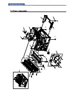
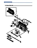
Page 103: ...Exploded Views Parts List 7 2 Frame Assembly 0 15 13 12 4 14 3 2 16 5 7 6 16 1 9 11 10 8 ...

Page 104: ...Exploded Views Parts List 7 3 Fuser Unit 0 1 2 33 4 32 3 5 6 7 8 9 10 11 12 13 14 15 16 17 18 19 34 25 24 23 20 21 22 26 27 28 29 30 31 6 7 ...

Page 105: ...Exploded Views Parts List 7 4 Paper Path Unit 0 1 2 3 4 5 25 6 7 8 9 9 1 9 2 9 3 11 11 1 11 2 11 3 12 13 14 16 16 15 17 18 19 20 21 24 23 26 24 22 ...

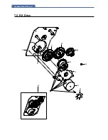
Page 106: ...Exploded Views Parts List 7 5 RX_Drive 0 6 3 4 9 10 8 7 11 2 5 ...

Page 107: ... 00031A SPRING ETC HV LARGE ML 6060A SUS 304 WP O1029 SA 7 1 15 2 JC70 40912A ICT SHAFT HV LARGE ML 5000A SWCH18A 4 O1100 SA 7 1 16 JC44 00079A HVPS SKYLARK 24V 21 6V 27 6V MAX 5KV O1026 SA 7 1 17 JC63 00722A SHEET HVPS ML 1610 PP PP T0 254 155 201 O1058 SA 7 1 18 JC63 00631A GROUND P HVPS ML 1610 SUS304CSP 1 2H 0 2 SNA 7 1 19 3903 000085 CBF POWER CORD DT US BP3 YES I IEC C13 C C0022 SA 7 1 20 JC...

Page 108: ...O1082 SA 7 4 3 JB61 00107A SPRING ETC LEVER SENSOR SF 430 SUS304 0 O1014 SA 7 4 4 JC70 10232A IPR PLATE SAW ML 80 SUS304 CSP 1 2H T0 O1099 SA 7 4 5 JC63 00625A GROUND P VARISTOR ML 1610 SUS304CSP1 2H SNA 7 4 7 JC63 00623A GROUND P THV ML 1610 SUS304CSP 1 2H 0 2 SNA 7 4 8 JC63 01125A GROUND P_SAW ML 2571N C5210P 0 2 54 5 49 SNA 7 4 9 JC97 02669A MEA UNIT HOLDER_PAD ML 2571N SAMSUNG O1122 SA 7 4 9 1...

Page 109: ... A 0501 000279 TR SMALL SIGNAL KSA1182 Y PNP 150mW SOT SA N A 0501 000457 TR SMALL SIGNAL MMBT2222A NPN 350mW SOT SA N A 0502 000245 TR POWER KSB1151 Y PNP 1 3W TO 126 16 SA N A 0801 002446 IC CMOS LOGIC 74LCX14 SCHMITT INVERTER T SNA N A 1003 001535 IC MOTOR DRIVER A3977SLP TSSOP 28P 9 6X4 SA N A 1006 001224 IC LINE TRANSCEIVER 74LVX161284 TSSOP 48 SA N A 1006 001250 IC LINE DRIVER DS90LV017A SOI...

Page 110: ... 120ohm 2012 TP SA N A 3301 000325 BEAD SMD 60ohm 3 2x2 5x1 3mm 400mA TP SNA N A 3702 000118 CONNECTOR RIBBON 36P FEMALE ANGLE AU SNA N A 3711 002001 HEADER BOARD TO CABLE BOX 20P 2R 2MM STR SA N A 3711 002810 HEADER BOARD TO CABLE BOX 9P 1R 2mm STRA SNA N A 3711 003035 HEADER BOARD TO CABLE BOX 14P 2R 2mm STR SA N A 3711 003408 HEADER BOARD TO CABLE BOX 2P 1R 2mm STRA SNA N A 3711 003409 HEADER B...

Page 111: ...R SPRING ML 2571N PET GF30 1 5 11 O1052 SA N A JC62 00145A SEAL SUPPLY ML 1610 CHLOROPRENE RUBBER SNA N A JC62 00146A SEAL SUPPORT L ML 1610 MICRO URETHANE SNA N A JC62 00147A SEAL SUPPORT R ML 1610 MICRO POLYURETHAN SNA N A JC62 00148A SEAL CAP SIDE ML 1610 POLYURETHANE FOAM SNA N A JC62 00149A SEAL CAP DEVE ML 1610 POLYURETHANE FOAM SNA N A JC62 00150A SEAL SUS BLADE ML 1610 POLYURETHANE FOAM SN...

Page 112: ...HEET SCX 4521F SEE EFGISPRS SNA N A JC68 01563A MANUAL 800 SEC CARD COMMON XAA ENGLISH E SNA N A JC68 01581A LABEL P CAUTION HOT COMMON SAMSUNG PET SNA N A JC68 01584A LABEL P BLANK 90 25 CLP 510 SEE ART 100 D2120 SA N A JC68 01709A MANUAL INSTALL ML 2570 SEC 16 WORLDWIDE1 SNA N A JC68 01722A LABEL BLANK SCX 4100 ART PAPER 0 15 16 4 SNA N A JC68 10909C LABEL P CAU LSU ML 1210 ART90G 55 80 SNA N A ...

Page 113: ... 00044A MEC BUSHING AGI L SF 5100 SEC POM SANTOP SNA N A JC92 01830A PBA MAIN LSU LD ML 2570 FR 4 8PIN 90 SNA N A JC94 01216A PHANTOM AU JC92 01803A SNA N A JC96 01730A ELA UNIT HOLDER TR L ML 6060A SAMSUNG SE O1112 SA N A JC96 03354A ELA UNIT DEV KIT 1K ML 1610 SEC INIT SNA N A JC96 04014A ELA HOU ENGINE ML 2571N SEC SNA N A JC96 04085A ELA UNIT LSU LD ML 2570 SINGLE 8PIN SNA N A JC97 01900B MEA ...

Page 114: ...Block diagram Service Manual 8 1 Samsung Electronics 8 8 8 Block Diagram 8 1 ML 2510 H W Block Diagram ...

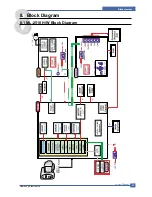
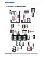
Page 115: ...Service Manual Block diagram 8 2 Samsung Electronics 8 2 ML 2570 2571N H W Block Diagram ...

Page 116: ...Connection Diagram Service Manual 9 1 Samsung Electronics 9 9 9 Connection Diagram 9 1 ML 2510 Connection Diagram ...

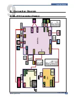
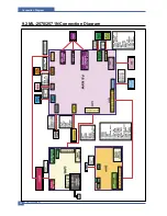
Page 117: ...Service Manual Connection Diagram 9 2 9 2 ML 2570 2571N Connection Diagram ...

Page 118: ... recommended safe and easy troubleshooting as described in this service manual DVM Digital Volt Meter Standard Indicates more than 3 digits Driver Standard type type M3 long M3 short M2 long M2 short Tweezers Standard For general home use small type Cotton Swab Standard For general home use for medical service Cleaning Equipments Standard An IPA Isopropyl Alcohol dry wipe tissue or a gentle neutra...

Page 119: ...ctor CPU Central Processing Unit dB decibel dbA decibel A dBM decibel milliwatt DC direct current DCU Diagnostic Control Unit DPI Dot Per Inch DRAM Dynamic Random Access Memory DVM Digital Voltmeter ECP Enhanced Capability Port EDC Embedded Diagnostic control EEPROM Electronically Erasable Programmable Read Only Memory EMI Electro Magnetic Interference EP electrophotographic EPP Enhanced Parallel ...

Page 120: ...shy place NVRAM nonvolatile random access memory OPC Organic Photo Conductor OPE Operate Panel Equipment PBA Printed Board Assembly PCL Printer Command Language Printer Control Language PDL Page Discription Language PPM Page Per Minute PPS Pulse Per Second PS Post Script PTL Pre Transfer Lamp PWM Pulse Width Modulation Q PID Quick Printer Initiating Device Q ty quantity RAM Random Access Memory RO...

Page 121: ...gh room to open the printer trays covers and allow for proper ventilation see diagram below Provide the proper environment A firm level surface Away from the direct airflow of air conditioners heaters or ventilators Free of extreme fluctuations of temperature sunlight or humidity Clean dry and free of dust ...

Page 122: ...terns shown below are the standard test patterns used in the factory The life of the toner cartridge developer cartridge and printing speed are measured with the pattern shown below The A4 ISO 19752 standard pattern samples are reproduced reduced to 70 of the actual A4 size A4 ISO 19752 Standard Patterns ...

Page 123: ... the PC1 Photo TRIAC is connected Then it emits light By this light the TRIAC unit a light receiving unit becomes on and electricity is supplied to the gate of the TRIAC Then the TRIAC is turned on As a result AC current flows in a heat lamp and the heat lamp radiates heat On the other contrary if the signal is turned off the PC1 becomes off and the TRIAC is turned off due to no elec tricity at th...

Page 124: ... 0250 2 3 2 1 3 2 1 Q2 MMBT2222ALT1 Q9 MMBT2222ALT1 CN1 1 Thermistor 2 3 1 DGND DGND 3 3V 3 3V DGND 5 U1 2 LM393D 6 1 8 1 GDI_Board 3 3V 3 3V 3 3V R10 15 4K 5 7 U1 2 LM393D 6 2 3 1 KDS226 THERM_IN nFUSER D3 DGND C11 1nF R1 470K Not Used C4 10nF R8 1K R15 7 5K 1 R3 14 7K 1 R12 33K R7 10K R20 5 1K DGND DGND DGND C15 10nF C12 100nF D7 KDS226 3 3V 3 3V R11 5 1K D1 MMSD914T1 FUSER_ON 1 35301 0250 2 3 2...

Page 125: ...rmally high At this time the resistance value of the thermister becomes low When the resistance value of the thermister becomes low the electric potential of the circled A gets low and when the temperature goes over the certain temperature the comparator U11 gets a low output As a result even though the fuser port is abnormally activated it is disable to be over the regular tem perature For mainta...

Page 126: ...n SFR Once the polygon motor regularly rotates it sends the page sync signal nPSync to PVC by writing 1 at LSUCON 5 in LSUC and PVC starts operating for one page printing After that every time nHSYNC signal is created PVC sens es the signal and outputs the video data PVC_VDO to LSUC At this time LSUC creates the video window Printing area and masks it on the video data sent by PVC LSUC sends the c...

Page 127: ...18 0 flagClear LSU_VDO LSU_CLK nPSync nLREADYFlag nHSYNC nLREADY_FO LSUC DAC PD THER THV DAC_OUT PI Control Block PRDATA 31 0 PWRITE APB BRIDGE APCCON 11 0 apcOnTime 20 0 apcOffTime 20 0 SHOffTime 20 0 SHOnTime 20 0 ENGIN ADC E Pmax 9 0 Pmin 9 0 Ka 14 0 REF 24 0 Kp 15 0 Ki 4 0 Ky YMAXH 8 0 YMAXL 31 0 YMINH 8 0 YMINL 31 0 YINITH 8 0 YINITL 31 0 KU 5 0 U_VALUE 25 0 SEH 4 0 SEL 4 0 L_VALUE 9 0 HCLR 2...

Page 128: ...version of 3 rd channel ends for the PI Control of LSU it sends the 10bit digital data converted with the latch short pulse signal to LSUC Name Direction Description PVC VDO I The video data output from PVC nLREADY I Its activity becomes low as the polygon motor of LSU gets the regular speed nHSYNC I It informs the beginning of one line It is the same as nLSYNC of PVC nPSync 0 It is inputted to nF...

Reviews: