


Samsung Electronics
Service Manual
System Overview
3-10
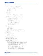
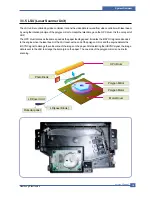
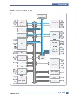
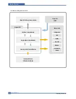
U6(Jupiter 4E for ML-2510 and SPGP V3 for ML-2570/2571N)
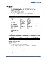
- ML-2510 use Jupiter4E which has a CPU core CLK with over 150MHz and a System bus 80MHz.
- It use 3.3V for operation voltage and I/O, It uses 80MHz for system bus CLK, Built in Flash Memory.
- ML-2570/2571N use SPGP V3 which has a CPU core CLK with over 400MHz and a System bus 100MHz.
SDRAM
- Main memory. SDCLK is 75Mhz for ML-2510, SDCLIC is 100Mhz for ML-2570/2571N.
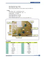
A3977
- It is an Main motor driver IC and controls the motion of main motor.
Regulator
- It Supplies the core voltage to CPU by converting 3.3V to 1.8V for ML-2510
EEPROM(U8 : 93C66 for ML-2510, 24C32 for ML-2570/2571N.
- It is an EEPROM with 12C method.
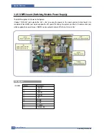
SMPS connector(CN8)
- It connects SMPS, supplies the power, and delivers the high voltage contol signal, etc. If a harness is not normally
connected to this connector, power cannot be supplied.
LSU connector(CN12)
- It connects a LSU.
DC Motor connector(CN11)
- It connects an main motor and drive a DC motor.
HVPS connector(CN10)
- It connects a HVPS.
DCU connector(CN1)
- It interface a DCU-JIG
USB connector(CN6)
- It interface the computer.
Network Connector(ML-2571N only)
- It interface the network
IEEE 1284 Parallel Connector
- It interface the computer.
DC To DC Converter
- It supplies the core sltage to CPU
by Converting 3.3V to 1.3V for ML-2570/2571N
Summary of Contents for ML-2510 series
Page 29: ...System Overview Samsung Electronics Service Manual 3 15 3 2 3 5 SPGPv3 Internal Block Diagram ...
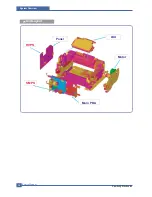
Page 103: ...Exploded Views Parts List 7 2 Frame Assembly 0 15 13 12 4 14 3 2 16 5 7 6 16 1 9 11 10 8 ...
Page 106: ...Exploded Views Parts List 7 5 RX_Drive 0 6 3 4 9 10 8 7 11 2 5 ...
Page 115: ...Service Manual Block diagram 8 2 Samsung Electronics 8 2 ML 2570 2571N H W Block Diagram ...
Page 117: ...Service Manual Connection Diagram 9 2 9 2 ML 2570 2571N Connection Diagram ...