


Disassembly and Reassembly
Samsung Electronics
Service Manual
5-5
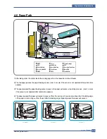
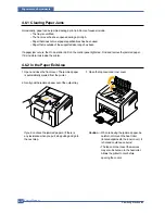
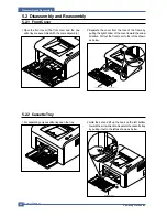
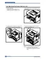
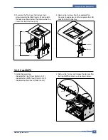
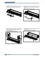
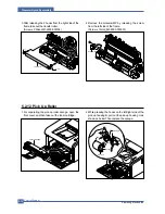
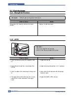
5. To remove the Top Cover, first remove the 4
screws securing the Side Cover(L,R) and unlatch
the hooks, as shown below. Then remove the Top
Cover from the Side Cover(L,R).
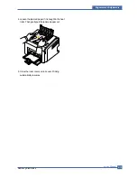
6. Remove the 2 screws from the separated Top
Cover as shown below, and then separate the LED
Lens from the On-Line Key.
Top Cover
Side
Cover, L
Side Cover, R
Main Cover
LED Lens
On-Line Key
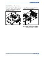
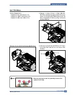
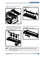
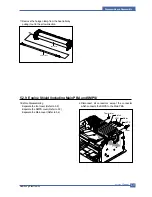
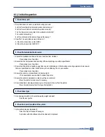
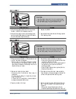
5.2.5 Cap-SMPS
1. Before Disassembling
- Separate the Front Cover (Refer to 5.2.1)
- Separate the SMPS Cover (Refer to 5.2.3)
- Separate the Main Cover (Refer to 5.2.4)
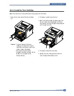
2. Remove the 1 screw and release the Harness from
the Cap-SMPS and remove it, as shown below.
Harness
Cap-SMPS
Summary of Contents for ML-2510 series
Page 29: ...System Overview Samsung Electronics Service Manual 3 15 3 2 3 5 SPGPv3 Internal Block Diagram ...
Page 103: ...Exploded Views Parts List 7 2 Frame Assembly 0 15 13 12 4 14 3 2 16 5 7 6 16 1 9 11 10 8 ...
Page 106: ...Exploded Views Parts List 7 5 RX_Drive 0 6 3 4 9 10 8 7 11 2 5 ...
Page 115: ...Service Manual Block diagram 8 2 Samsung Electronics 8 2 ML 2570 2571N H W Block Diagram ...
Page 117: ...Service Manual Connection Diagram 9 2 9 2 ML 2570 2571N Connection Diagram ...


