


4-16
Samsung Electronics
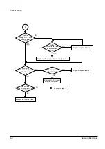
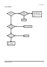
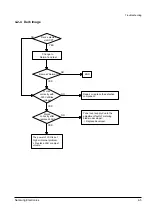
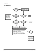
Troubleshooting
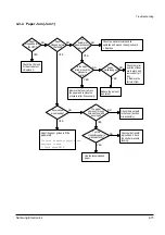
4-4 DCU Control
4-4-1 DCU Setup
DCU is used to diagnose the printer malfunctions. To use DCU, open and remove the Printer’s exit cover in
front, and remove the bottom cover from left. Connect the DCU harness wire (10 pin-to-4 pin) to CN9 (4 pins)
on the control board.
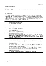
4-4-2 Status Code
Connect the DCU to the printer and turn power on. The DCU display Status Code in the 7 segment LEDs.
There are two kinds of Status Codes; Normal and Error. And their codes mean the printer operating status.
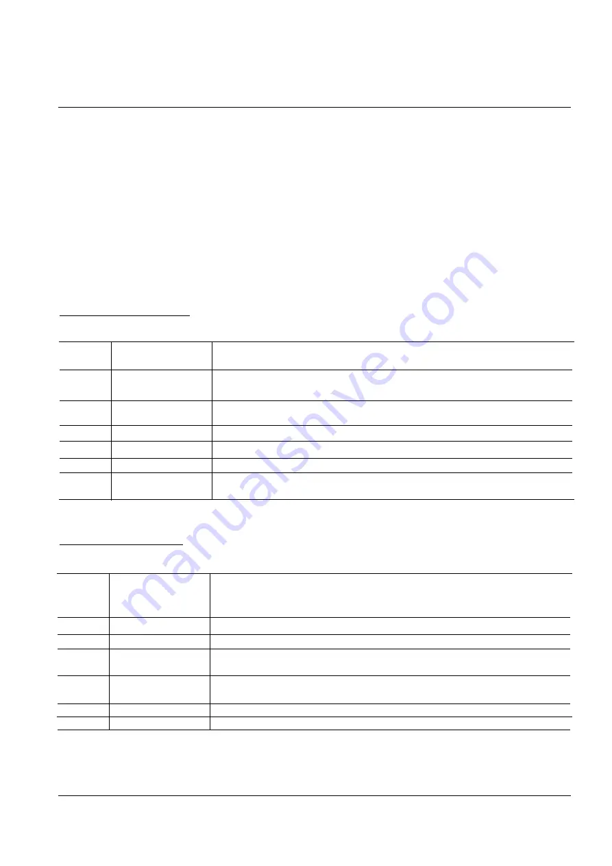
NORMAL STATUS CODE
These codes mean paper location on the paper path when the printer is printing, or warming up.
61
Warm up
The printer warms up when the printer is turned on or the cover is closed, or
wake from sleep mode.
00~04
Ready(paper type)
The printer is in printable state. The paper type is sensed after
one page printing.
20
Print Start
The code is displayed when engine controller is received ‘PRINT’ command
from the video controller.
30
Feed Sensor On
It means that paper is passing the feed sensor.
40
Feed Sensor Off
It means that paper passed the feed sensor.
50
Paper out
It means that paper passed the exit sensor.
69
Sleep Mode
It means that the printer fuser is turned off, and the power consumption is
minimized.
ERROR STATUS CODE
If the printer stops printing by any malfunction, the DCU displays its error status code.
60,62,68
Fuser Error
These codes mean the fuser error status. Heat lamp, thermistor, thermostat
open or thermistor short. The ‘Low Temperature Error’ is checked when the
printer is printing.
64
Cover Open
The printer cover open or no toner cartridge in the machine.
70
No Paper
The paper is not loaded in the printer paper tray.
71
Paper Jam 0
Displays when the paper leading edge stops between the pick-up unit and
the feed sensor.
72
Paper Jam 1
Displays when the paper leading edge stops between the feed sensor and
the exit sensor.
73
Paper Jam 2
Displays when the paper leading edge stops after the exit sensor.
95
LSU Not Ready
The LSU scanner motor is not ready or ‘Hsync’ signal is not output.
Summary of Contents for ML-5200A
Page 50: ...5 14 Samsung Electronics Exploded Views and Parts List MEMO ...
Page 63: ...PCB Diagrams Samsung Electronics 9 5 9 5 HVPS PCB Diagram TOP ...
Page 68: ...MEMO Samsung Electronics 8 2 ...
Page 69: ...10 1 Main Circuit Diagram 1 9 Samsung Electronics 10 1 10 Schematic Diagrams ...
Page 70: ...Schematic Diagrams 10 2 Samsung Electronics Main Circuit Diagram 2 9 ...
Page 71: ...Main Circuit Diagram 3 9 Samsung Electronics 10 3 Schematic Diagrams ...
Page 72: ...Schematic Diagrams 10 4 Samsung Electronics Main Circuit Diagram 4 9 ...
Page 73: ...Main Circuit Diagram 5 9 Samsung Electronics 10 5 Schematic Diagrams ...
Page 74: ...Schematic Diagrams 10 6 Samsung Electronics Main Circuit Diagram 6 9 ...
Page 75: ...Main Circuit Diagram 7 9 Samsung Electronics 10 7 Schematic Diagrams ...
Page 76: ...Schematic Diagrams 10 8 Samsung Electronics Main Circuit Diagram 8 9 ...
Page 77: ...Main Circuit Diagram 9 9 Samsung Electronics 10 9 Schematic Diagrams ...
Page 78: ...Schematic Diagrams 10 10 Samsung Electronics 10 2 Engine Circuit Diagram 1 2 ...
Page 79: ...Engine Circuit Diagram 2 2 Samsung Electronics 10 11 Schematic Diagrams ...
Page 80: ...Schematic Diagrams 10 12 Samsung Electronics 10 3 SMPS Circuit Diagram ...
Page 81: ...10 4 SENSOR Circuit Diagram Samsung Electronics 10 13 Schematic Diagrams ...
Page 82: ...Schematic Diagrams 10 14 Samsung Electronics 10 5 PTL Circuit Diagram ...
Page 83: ...10 6 HVPS Circuit Diagram 1 3 Samsung Electronics 10 15 Schematic Diagrams ...
Page 84: ...Schematic Diagrams 10 16 Samsung Electronics HVPS Circuit Diagram 2 3 ...
Page 85: ...HVPS Circuit Diagram 3 3 Samsung Electronics 10 17 Schematic Diagrams ...


