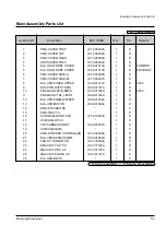
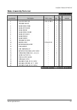
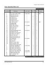

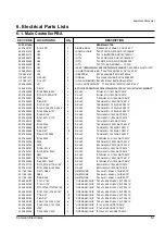


SEC CODE LOCATION NO. Q’ty DESCRIPTION
JC92-01144B
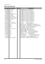
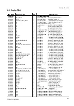
PBA MAIN-TEPIN ENGINE
0401-000005
“D3,D4,D5,D7”
4
DIODE-SWITCHING
“1N4148,100V,200MA,DO-35,TP”
0402-000129
“D1,D2”
2
DIODE-RECTIFIER
“1N4003,200V,1A,DO-41,TP”
0501-000010
“Q1,Q2,Q4,Q5,Q6,Q7,Q8,Q11”
8
TR-SMALL SIGNAL
“KSC1008,NPN,800mW,TO-92,TP,120”
0501-000294
Q9
1
TR-SMALL SIGNAL
“KSA708-Y,PNP,800mW,TO-92,TP,12”
0604-001106
U1
1
PHOTO-INTERRUPTER“TR,25%-,-,-,BK”
0801-000528
U2
1
IC-CMOS LOGIC
“74HCT574,D FLIP-FLOP,DIP,20P,3”
0803-001097
U6
1
IC-TTL
“7407,BUFFER/DRIVER,DIP,14P,300”
0803-001182
U8
1
IC-TTL
“74F08,AND GATE,DIP,14P,300MIL,”
0903-000219
U4
1
IC-MICROCOMPUTER “88C4316,8BIT,DIP,64P,-,8MHz,ST”
1003-001165
U5
1
IC-MOTOR DRIVER
“SMA7029M,ANGLE,15P,31MIL,*,1.5”
1103-001045
U3
1
IC-EEPROM
“27E512,64Kx8BIT,DIP,28P,600MIL”
1202-000103
U7
1
IC-VOLTAGE COMP.
“393,DIP,8P,300MIL,DUAL,36V,CMO”
2001-000003
“R10,R63”
2
R-CARBON
“330ohm,5%,1/8W,AA,TP,1.8x3.2mm”
2001-000006
“R12,R17”
2
R-CARBON
“2.4KOHM,5%,1/8W,AA,TP,1.8X3.2MM”
2001-000221
R39
1
R-CARBON
“1.2KOHM,5%,1/8W,AA,TP,1.8X3.2MM”
2001-000281
“R1,R23,R25,R26,R44,R45”
6
R-CARBON
“100OHM,5%,1/8W,AA,TP,1.8X3.2MM”
2001-000331
R70
1
R-CARBON
“12KOHM,5%,1/8W,AA,TP,1.8X3.2MM”
2001-000362
“R9,R21,R24”
3
R-CARBON
“150OHM,5%,1/8W,AA,TP,1.8X3.2MM”
2001-000429
“R4,R7,R20,R40,R48,R49,R59,R68”
8
R-CARBON
“1KOHM,5%,1/8W,AA,TP,1.8X3.2MM”
2001-000515
R46
1
R-CARBON
“220OHM,5%,1/8W,AA,TP,1.8X3.2MM”
2001-000660
“R66,R100”
2
R-CARBON
“33KOHM,5%,1/8W,AA,TP,1.8X3.2MM”
2001-000723
R58
1
R-CARBON
“4.3KOHM,5%,1/8W,AA,TP,1.8X3.2MM”
2001-000723
R62
1
R-CARBON
“4.3KOHM,5%,1/8W,AA,TP,1.8X3.2MM”
2001-000786
“R15,R16,R64”
3
R-CARBON
“47KOHM,5%,1/8W,AA,TP,1.8X3.2MM”
2001-000812
“R2,R3,R8,R19,R27,R28,R32~R35”
10
R-CARBON
“5.6KOHM,5%,1/8W,AA,TP,1.8X3.2MM”
2001-000812
“R36~R38,R41~,R43,R51~R53”
9
R-CARBON
“5.6KOHM,5%,1/8W,AA,TP,1.8X3.2MM”
2001-000812
“R54,R55,R56,R67”
4
R-CARBON
“5.6KOHM,5%,1/8W,AA,TP,1.8X3.2MM”
2001-000832
“R14,R29,R71”
3
R-CARBON
“510OHM,5%,1/8W,AA,TP,1.8X3.2MM”
2001-000857
R22
1
R-CARBON
“560OHM,5%,1/8W,AA,TP,1.8X3.2MM”
2001-000864
R69
1
R-CARBON
“56KOHM,5%,1/8W,AA,TP,1.8X3.2MM”
2003-000547
“R11,R13”
2
R-METAL OXIDE(S)
“1ohm,5%,3W,AA,TP,6x16mm”
2004-000345
“R6,R18,R30,R31,R65”
5
R-METAL
“15Kohm,1%,1/8W,AA,TP,1.8x3.2mm”
2004-000433
R57
1
R-METAL
“1Kohm,1%,1/8W,AA,TP,1.8x3.2mm”
2004-000699
R61
1
R-METAL
“3.3Kohm,1%,1/8W,AA,TP,1.8x3.2m”
2201-000017
“C7,C13,C14,C17,C19,C21,C36,C37,C41”
9
“C-CERAMIC,DISC”
“1nF,10%,50V,Y5P,TP,5x3.5,5”
2201-000019
“C6,C10,C28,C31,C32,C35,C38”
7
“C-CERAMIC,DISC”
“10nF,+80-20%,500V,Y5V,TP,13.5x4mm,5”
2201-000119
“C1,C5,C11,C16,C29,C30,C43,C45”
8
“C-CERAMIC,DISC”
“100nF,+80-20%,50V,Y5V,TP,8x3,5”
2201-000138
“C33,C34”
2
“C-CERAMIC,DISC”
“100pF,10%,50V,Y5P,TP,4.0X4.0,2”
2201-000326
“C8,C18”
2
“C-CERAMIC,DISC”
“2.2nF,10%,50V,Y5P,TP,7x3,5”
2201-000391
“C23,C24”
2
“C-CERAMIC,DISC”
“0.022nF,5%,50V,SL,TP,5x3,5”
2201-000558
“C4,C9,C25,C26”
4
“C-CERAMIC,DISC”
“0.47nF,10%,50V,Y5P,TP,5x3,5”
2202-000002
“C15,C22”
2
“C-CERAMIC,MLC-AXIAL”“10nF,0.05,500V,X7R,TP,5.1x6.4x”
2202-000173
“C39,C40”
2
“C-CERAMIC,MLC-AXIAL”“1nF,10%,50V,Y5P,TP,1.9x3.5,-”
2401-002075
“C42,C46”
2
C-AL
“4.7uF,20%,50V,GP,TP,5x11,5”
2401-002144
“C2,C27”
2
C-AL
“47uF,20%,16V,GP,TP,5x11,5”
2401-002300
C3
1
C-AL
“47uF,20%,50V,GP,TP,6.3x11,5”
2801-000002
OSC1
1
CRYSTAL-UNIT
“6.94407MHz,50ppm,28-AAM,20pF,5”
3301-000344
“BD1,BD2,BD3,BD4,BD5”
5
CORE-FERRITE BEAD “ZZ,3.5x6.5mm,-,-”
3704-000235
U3
1
SOCKET-IC
“28P,DIP,SN,2.54mm”
3711-000588
CN7
1
CONNECTOR-HEADER“BOX,10P,1R,2.5mm,STRAIGHT,SN”
3711-000961
CN6
1
CONNECTOR-HEADER“BOX,4P,1R,2.5mm,STRAIGHT,SN”
3711-002807
CN2
1
CONNECTOR-HEADER“BOX,6P,1R,2mm,STRAIGHT,SN”
3711-003204
CN1
1
CONNECTOR-HEADER“BOX,24P,2R,2mm,STRAIGHT,SN”
Electrical Parts List
Samsung Electronics
6-3
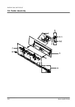
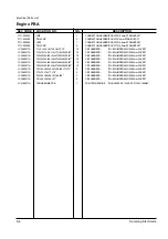
6-2. Engine PBA
Summary of Contents for ML-5200A
Page 50: ...5 14 Samsung Electronics Exploded Views and Parts List MEMO ...
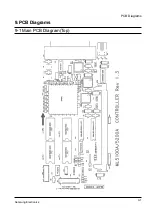
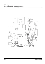
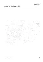
Page 63: ...PCB Diagrams Samsung Electronics 9 5 9 5 HVPS PCB Diagram TOP ...
Page 68: ...MEMO Samsung Electronics 8 2 ...
Page 69: ...10 1 Main Circuit Diagram 1 9 Samsung Electronics 10 1 10 Schematic Diagrams ...
Page 70: ...Schematic Diagrams 10 2 Samsung Electronics Main Circuit Diagram 2 9 ...
Page 71: ...Main Circuit Diagram 3 9 Samsung Electronics 10 3 Schematic Diagrams ...
Page 72: ...Schematic Diagrams 10 4 Samsung Electronics Main Circuit Diagram 4 9 ...
Page 73: ...Main Circuit Diagram 5 9 Samsung Electronics 10 5 Schematic Diagrams ...
Page 74: ...Schematic Diagrams 10 6 Samsung Electronics Main Circuit Diagram 6 9 ...
Page 75: ...Main Circuit Diagram 7 9 Samsung Electronics 10 7 Schematic Diagrams ...
Page 76: ...Schematic Diagrams 10 8 Samsung Electronics Main Circuit Diagram 8 9 ...
Page 77: ...Main Circuit Diagram 9 9 Samsung Electronics 10 9 Schematic Diagrams ...
Page 78: ...Schematic Diagrams 10 10 Samsung Electronics 10 2 Engine Circuit Diagram 1 2 ...
Page 79: ...Engine Circuit Diagram 2 2 Samsung Electronics 10 11 Schematic Diagrams ...
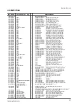
Page 80: ...Schematic Diagrams 10 12 Samsung Electronics 10 3 SMPS Circuit Diagram ...
Page 81: ...10 4 SENSOR Circuit Diagram Samsung Electronics 10 13 Schematic Diagrams ...
Page 82: ...Schematic Diagrams 10 14 Samsung Electronics 10 5 PTL Circuit Diagram ...
Page 83: ...10 6 HVPS Circuit Diagram 1 3 Samsung Electronics 10 15 Schematic Diagrams ...
Page 84: ...Schematic Diagrams 10 16 Samsung Electronics HVPS Circuit Diagram 2 3 ...
Page 85: ...HVPS Circuit Diagram 3 3 Samsung Electronics 10 17 Schematic Diagrams ...