background image

GB

7

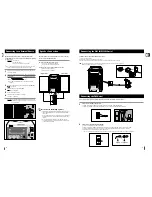
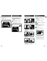
The main lead must be plugged into an appropriate socket.

Before plugging your system into a main socket, you must check
the voltage.

Check the position of the voltage selector on the bottom of the 
system (OPTION).

Plug the main lead (marked 

AC Cord

on the rear of the system) into

an appropriate socket.

Press the 

On/Standby

button to switch your micro-component system on.

To take full advantage of your new micro-component system, fol-
low these installation instructions before connecting the unit.

Install the system on a flat, stable surface.

Never place this unit on carpeting.

Never place this unit in an outdoor area.

Maintain an open space of approximately 6 inches (15 cm) on the
sides and rear of the system, for ventilation purposes.

Make sure that you have enough room to open the compact disc
compartment easily.

Place the loudspeakers at a reasonable distance on either side of
the system to ensure good stereo sound.

Direct the loudspeakers towards the listening area.

For optimum performance, make sure that both speakers are placed
at an equal distance above the floor.

Where to Install Your 
Micro-Component System

Connecting your System to the
Power Supply

2

3

B

6

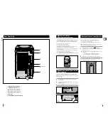
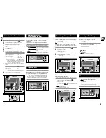
Rear Panel View

1. MIC Jack Connector(optional)

2.   Headphone Jack Connector

3. FM Aerial Connector Terminal

4. AM Aerial Connector Terminal

5. AUX-Input

6. Loudspeakers Connector Terminals

Insert or replace remote control batteries when you:

Purchase the

micro-component

system

Find that the remote control is no longer operating correctly

When replacing the batteries, use a new set of batteries and
never mix alkaline and manganese batteries.

Place your thumb on the position marked

on the battery 

compartment cover (rear of the remote control) and push the cover in
the direction of the arrow.

Insert two AAA, LR03 or equivalent batteries, taking care to respect
the polarities:

+ on the battery a in the battery compartment

– 

on the battery against – in the battery compartment

Replace the cover by sliding it back until it clicks into position.

If you will not be using the remote control for a long time,
remove the batteries to prevent corrosion.

1

2

3

ANTENNA

AC CORD

EQ

Down

Mute

Counter

Reset

Repeat
A     B

Tuning Mode

REC/Pause

CD Sync.

Up

S.Bass

Volume

Power
Sound

Push Eject

CD

AUX

TUNER

TAPE

Band

1

2

3

4

AC CORD

6

1

2

5

(Rear)

(Bottom) 

1

220V-240V   110V-127V

Inserting Remote Control Batteries

Summary of Contents for MM-B3

Page 1: ...Instruction Manual MICRO COMPONENT SYSTEM CD R RW PLAYBACK MM B3 B4...

Page 2: ...CTRIC SHOCK DO NOT EXPOSE THIS APPLIANCE TO RAIN OR MOISTURE CAUTION TO PREVENT ELECTRIC SHOCK MATCH WIDE BLADE OF PLUG TO WIDE SLOT FULLY INSERT CAUTION TO REDUCE THE RISK OF ELECTRIC SHOCK DO NOT RE...

Page 3: ...ay 18 Volume increase 19 Tuning Mode 20 Volume decrease On Standby Timer On Off TAPE EQ Preset Power Sound Sleep CD Repeat Mono ST TUNER Band Program Set AUX Timer Clock CD CD CD VOL VOL Tuning Mode 1...

Page 4: ...e to Install Your Micro Component System Connecting your System to the Power Supply 2 3 B 6 Rear Panel View 1 MIC Jack Connector optional 2 Headphone Jack Connector 3 FM Aerial Connector Terminal 4 AM...

Page 5: ...idity may cause performance degradation of the speaker Do not install on the wall or on a high place of pole or other unsta ble place to prevent any safety accident caused by falling of the speaker Do...

Page 6: ...n before using this function Searching for a Specific Music Passage on a CD CD CD VOL VOL Tuning Mode On Standby Timer On Off EQ Preset Power Sound Sleep CD Repeat Mono ST TUNER Band Program Set AUX T...

Page 7: ...and Storing the Radio Stations 6 1 EQ Down Mute Counter Reset Repeat A B Tuning Mode REC Pause CD Sync Up S Bass Volume Power Sound CD AUX TUNER TAPE Band 1 15 AM stations option 15 AM stations optio...

Page 8: ...on the recording Switch your system on by pressing On Standby Insert a blank cassette in Deck Load a compact disc Press the CD button Use the CD selection buttons to select the desired song Press the...

Page 9: ...the middle right of the time indicating that the timer has been set The system will switch on and off automatically at the required times If the timer switch on and off times are identical the word ER...

Page 10: ...o heating appliances or in direct sunlight etc If the unit emits an unpleasant odor when in use unplug it from the main supply and contact the after sales service Cleaning Your Micro Component System...

Page 11: ...on The main lead is not correctly plugged into a wall socket or the wall socket is not switched on The remote control batteries need replacing or the polarity has not been respected The On Standby but...

Page 12: ...ELECTRONICS THIS APPLIANCE IS MANUFACTURED BY AH68 01205B...

Reviews: