Contents
1. Precaution
1-1 Safety Precautions ........................................................................................... 1-1
1-2 Servicing Precautions ......................................................................................1-3
1-3 Precautions for Electrostatically Sensitive Devices (ESDs) ............................. 1-4
2. Product Specification
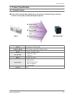
2-1 Product Feature ............................................................................................... 2-1
2-2 Specifications ................................................................................................... 2-2
2-3 Specifications Analysis .....................................................................................2-4
2-4 Accessories ...................................................................................................... 2-5
3. Disassembly & Reassembly
3-1 Overall Disassembly & Reassembly ................................................................3-1
4. Troubleshooting
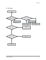
4-1 Checkpoints by Error Mode..............................................................................4-2
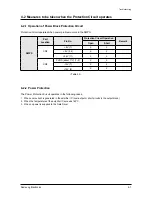
4-2 Measures to be taken when the Protection Circuit operates ........................... 4-7
4-3 DVD flash Initialization & Update ...................................................................4-8
5. Exploded View & Part List
5-1 Exploded View ................................................................................................. 5-2
5-2 Electrical Part List ............................................................................................ 5-4
6. PCB Diagram
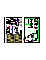
6-1 Wiring Diagram ................................................................................................ 6-2
6-2 MIC PCB Top ................................................................................................... 6-3
6-3 MIC PCB Bottom .............................................................................................. 6-5
6-4 FRONT PCB Top .............................................................................................. 6-6
6-5 FRONT PCB Bottom ........................................................................................6-8
6-6 MAIN PCB Top ................................................................................................. 6-9
6-7 MAIN PCB Bottom ........................................................................................... 6-11
6-8 MPEG PCB Top ............................................................................................... 6-13
6-9 MPEG PCB Bottom .......................................................................................... 6-15
6-10 SMPS PCB Top ................................................................................................ 6-16
6-11 SMPS PCB Bottom .......................................................................................... 6-18
6-12 CD PCB Top ..................................................................................................... 6-19
Summary of Contents for MM-DA25
Page 34: ...Samsung Electronics 6 3 PCB Diagram 6 2 MIC PCB Top 1 2 MCON11 UJ2 ...
Page 36: ...Samsung Electronics 6 5 PCB Diagram 6 3 MIC PCB Bottom MCON11 UJ2 ...
Page 37: ...6 6 Samsung Electronics PCB Diagram 1 2 6 4 FRONT PCB Top MCW1 VFD1 UJ11 ...
Page 39: ...6 8 Samsung Electronics PCB Diagram 6 5 FRONT PCB Bottom MCW1 VFD1 UJ11 UIC2 HIC2 MIC1 ...
Page 43: ...6 12 Samsung Electronics PCB Diagram 6 7 1 Test Point Wave Form TP1 TP2 ...
Page 46: ...Samsung Electronics 6 15 PCB Diagram 6 9 MPEG PCB Bottom MIC1 BIC4 DIC3 VIC1 IC4 IC3 IC2 ...
Page 47: ...6 16 Samsung Electronics PCB Diagram 1 6 10 SMPS PCB Top CON3 IC1 ...
Page 49: ...6 18 Samsung Electronics PCB Diagram 6 11 SMPS PCB Bottom CON3 ...


