background image

6-1

Samsung Electronics

- This Document can not be used without Samsung’s authorization -

6. Schematic Diagram

6-1 CD  Part

Summary of Contents for MM-J5

Page 1: ...ENT SYSTEM MM J5 SERVICEManual MICRO COMPONENT SYSTEM CONTENTS 1 Alignment and Adjustments 2 Exploded Views and Parts List 3 Electrical Parts List 4 Block Diagrams 5 Wiring Diagram 6 Schematic Diagrams Confidential ...

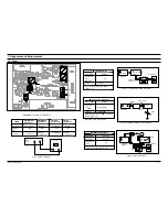
Page 2: ... 28 dB FM S S G Output GND Speaker Terminal FM Antenna Terminal Distortion Meter Input SET Input output Oscilloscope FM IN FM Antenna SET 10 kΩ AM SSG 450KHZ INPUT AM ANT IN Speaker Terminal 60cm AM IF VTVM Oscilloscope AM MW I F Adjustment Maximum output Figure 1 3 SSG FREQ Frequency Adjustment point 450 kHz 522 kHz AA Figure1 3 AM I F Adjustment OUTPUT Adjustment Location of Tuner PCB Fig 1 4 OS...

Page 3: ...er adjustment secureitwith REGION LOCK Remark Standard To Adjust Pre Setup Item Step Pre Setup Condition AfterputtingMTT 114NintoDeck1 PressFWDPLAY button 1 2 Turn thecontrol screwtoasshownin Figure1 6 MAX OUTPUT and same phase both channels CHECK TO 7mV 0 5mV Remark Standard To Adjust Pre Setup Item Step Pre Setup Condition AfterputtingMTT 5512intoDeck2 1 PressRECPLAYbutton 2 TAPEPCBJCW3 connecte...

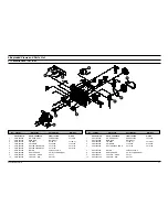
Page 4: ...CM09 120L2 6 8 AH81 00543H REEL SENSOR SG 107F3 KODENSHI 9 AH81 00543J LEAF S W WHITE SPLFF 10 AH81 00543K LEAF S W BLK SPLFE1 No Code No Description Specification Remarks AH59 01267A DECK CASSETTE CMAL1Z230A A REV 1 AH81 00543A R P HEAD ASS Y HADKH5655A F513 853 2 AH81 00733A MAIN BELT MAIN BELT 3 AH81 00543C F R BELT FF19S 31 FF19S 31 4 AH81 00543D SOLENOID F765 292 F765 292 5 AH81 00543E ROLLER...

Page 5: ...2 2 Total Exploded View and Parts List Samsung Electronics 2 2 ...

Page 6: ... Parts List of The Exploded View Samsung Electronics 2 3 ...

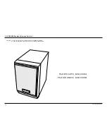
Page 7: ...2 3 SPEAKER Exploded View and Parts list CAUTION It is used the bonding connect FRONT PANEL to CABINET WOODEN So when the disassembly take extreme care not to damage the SPEAKER Samsung Electronics 2 4 ...

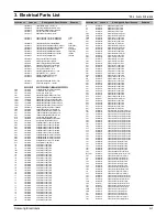
Page 8: ...TP 3216 R501L 2007 000282 R CHIP 100Kohm 5 1 8W TP 2012 R501R 2007 000282 R CHIP 100Kohm 5 1 8W TP 2012 R502R 2007 000290 R CHIP 100ohm 5 1 8W TP 2012 R132 2007 000300 R CHIP 10Kohm 5 1 8W TP 2012 R133 2007 000300 R CHIP 10Kohm 5 1 8W TP 2012 R108 2007 000308 R CHIP 10ohm 5 1 8W TP 2012 R124 2007 000338 R CHIP 120Kohm 5 1 8W TP 2012 R125 2007 000338 R CHIP 120Kohm 5 1 8W TP 2012 R117 2007 000355 R...

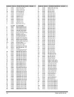
Page 9: ...8X3 2MM UR101 2001 000429 R CARBON 1KOHM 5 1 8W AA TP 1 8X3 2MM UR111 2001 000429 R CARBON 1KOHM 5 1 8W AA TP 1 8X3 2MM UR64 2001 000449 R CARBON 2 2KOHM 5 1 8W AA TP 1 8X3 2M UR55 2001 000449 R CARBON 2 2KOHM 5 1 8W AA TP 1 8X3 2M UR56 2001 000591 R CARBON 3 3KOHM 5 1 8W AA TP 1 8X3 2M UR63 2001 000591 R CARBON 3 3KOHM 5 1 8W AA TP 1 8X3 2M JW25 2007 000029 R CHIP 0ohm 5 1 8W TP 2012 JW7 2007 000...

Page 10: ...IGNAL KTA1273 PNP 30V 30V 2 CQ4 0501 000422 TR SMALL SIGNAL KTA1273 PNP 30V 30V 2 CQ3 0501 000422 TR SMALL SIGNAL KTA1273 PNP 30V 30V 2 JQ2R 0501 002184 TR SMALL SIGNAL KTD1304 NPN 200mW SOT 23 JQ2L 0501 002184 TR SMALL SIGNAL KTD1304 NPN 200mW SOT 23 JQ1R 0501 002184 TR SMALL SIGNAL KTD1304 NPN 200mW SOT 23 JQ1L 0501 002184 TR SMALL SIGNAL KTD1304 NPN 200mW SOT 23 CQ8 0501 002408 TR SMALL SIGNAL ...

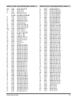
Page 11: ...RAMIC MLC AXIAL 4 7nF 20 16V Y5R TP AC6R 2202 000817 C CERAMIC MLC AXIAL 4 7nF 20 16V Y5R TP AC6L 2202 000817 C CERAMIC MLC AXIAL 4 7nF 20 16V Y5R TP EC1R 2203 000239 C CER CHIP 0 1NF 5 50V C0G TP 2012 EC1L 2203 000239 C CER CHIP 0 1NF 5 50V C0G TP 2012 JC6L 2203 000260 C CER CHIP 10nF 10 50V X7R TP 2012 JC7R 2203 000323 C CER CHIP 12nF 10 50V X7R TP 2012 JC7L 2203 000323 C CER CHIP 12nF 10 50V X7...

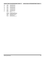
Page 12: ...01 002180 C AL 2 2uF 20 50V GP TP 5x11mm 5mm FC2R 2401 002180 C AL 2 2uF 20 50V GP TP 5x11mm 5mm FC3L 2401 002180 C AL 2 2uF 20 50V GP TP 5x11mm 5mm JL1 2701 000298 INDUCTOR AXIAL 470uH 10 4298 RIC2 AC14 12001G IC KA78L05 T AH41 00627A PCB MAIN MM J4 J6 FR1 1 1 6T 197 247 AH97 01246A ASSY CA DECK MM J4 ASSY CA DECK 6002 000398 SCREW TAPPING BH 2 M3 L6 ZPC YEL SWCH AH39 00360B LEAD CONNECTOR MM J6 ...

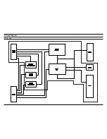
Page 13: ...4 1 Samsung Electronics 4 Block Diagram 4 1 CD Part ...

Page 14: ...Samsung Electronics 5 1 5 Wiring Diagram ...

Page 15: ...6 1 Samsung Electronics This Document can not be used without Samsung s authorization 6 Schematic Diagram 6 1 CD Part ...

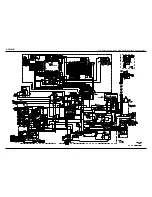
Page 16: ...Samsung Electronics 6 2 This Document can not be used without Samsung s authorization 6 2 MAIN ...

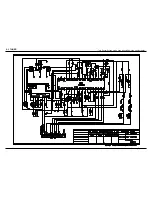
Page 17: ...6 3 Samsung Electronics This Document can not be used without Samsung s authorization 6 3 TUNER ...

Page 18: ...MM J5 ELECTRONICS Samsung Electronics Co Ltd MAY 2004 Printed in Korea Code no AH68 01543X ...

Reviews: