background image

1. Precautions

Follow these safety, servicing and ESD precautions to prevent damage and protect against potential hazards
such as electrical shock and X-rays.

Samsung Electronics

1-1

1-1 Safety Precautions

1. Be sure that all of the built-in protective

devices are replaced.  

2. When reinstalling the chassis and its 

assemblies, be sure to restore all protective

devices, including control knobs and 

compartment covers.

3. Make sure that there are no cabinet 

openings through which people--
particularly children--might insert fingers

and contact dangerous voltages.  Such
openings include the spacing between the
picture tube and the cabinet mask, 

excessively wide cabinet ventilation slots,

and improperly fitted back covers.

4. Design Alteration Warning:

Never alter or add to the mechanical or
electrical design of the unit. Example: Do
not add auxiliary audio or video connec-
tors. Such alterations might create a safety
hazard. Also, any design changes or addi-
tions will void the  manufacturer's warran-
ty.

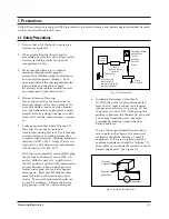
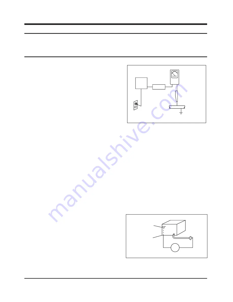
5. Leakage Current Hot Check (Figure 1-1):

Warning: Do not use an isolation 
transformer during this test.  Use a leakage-

current tester or a metering system that
complies with American National Standards
Institute (ANSI  C101.1, 

Leakage Current for

Appliances

), and Underwriters Laboratories

(

UL Publication UL1410, 59.7

).

With the unit completely reassembled, plug

the AC line cord directly into a 120V AC
outlet.  With the unit's AC switch first in
the ON position and then OFF, measure the
current between a known earth ground
(metal water pipe, etc.) and all exposed
metal parts.  Examples: Handle brackets,
metal cabinets, screwheads and control
shafts.  The current measured should not
exceed 0.5 milliamp.  Reverse the power-
plug prongs in the AC outlet and repeat.

6. Insulation Resistance Cold Check:  

(1) With the unit's AC plug disconnected
from the AC source, connect an electrical
jumper across the two AC prongs.  (2) Set
the power switch to ON.  (3) Measure the
resistance between the shorted AC plug and
any exposed metallic parts.  Example:
Screwheads, antenna, control shafts or 
handle brackets.

If any of the exposed metallic parts has a
return path to the chassis, the measured
resistance should be  between 1 and 5.2
megohms.  If there is no return path, the
measured resistance should be "infinite."  If
the resistance is outside these limits, a shock
hazard might exist.  See Figure 1-2

Device
Under 

Test

(Reading should
not be above
0.5mA)

Leakage
Currant
Tester

Earth
Ground

Test all

exposed metal

surfaces

Also test with
plug reversed
(using AC adapter
plug as required)

2-Wire Cord

Antenna
Terminal

Exposed
Metal Part

ohm

Ohmmeter

Fig. 1-1 AC Leakage Test

Fig. 1-2 Insulation Resistance Test

Summary of Contents for MM-X7

Page 1: ...MICRO COMPONENT SYSTEM BASIC MODEL MM X7 DX7 KX7 SERVICEManual MICRO COMPONENT SYSTEM Features MP3 CD DVD CD R RW Playback USB HOST Tuner Confidential...

Page 2: ...rent for Appliances and Underwriters Laboratories UL Publication UL1410 59 7 With the unit completely reassembled plug the AC line cord directly into a 120V AC outlet With the unit s AC switch first i...

Page 3: ...plug the unit s AC power cord from the AC power source before attempting to a Remove or reinstall any component or assembly b Disconnect an electrical plug or connector c Connect a test component in p...

Page 4: ...eady to install it Most replacement ESDs are packaged with leads that are electrically shorted together by conductive foam aluminum foil or other conductive materials 8 Immediately before removing the...

Page 5: ...plane which is grounded 3 The repair technician must wear a wrist strap which is grounded to the copper sheet 4 To remove the Optical Pickup block Place the set on the conductive sheet and momentaril...

Page 6: ...n disc the disc can be played only up to the blank segment A maximum of 9 999 images can be stored on a single CD When playing a Kodak Fuji Picture CD only the JPEG files in the picture folder can be...

Page 7: ...tio Channel separation Input sensitivity G E N E R A L T U N E R F M T U N E R MW VIDEO OUTPUT A M P L I F I E R 60W 4 3Kg 170 x 175 x 292 mm 5 C 35 C 10 75 10dB 55dB 0 8 56dB 40dB 2 1 0Vp p 75 load Y...

Page 8: ...X7 KOREA AH59 01787E REMOCON ASSY MM X7 NOEUR SAMSUNG 172 48 MM X7 EXP AH59 01787A REMOCON ASSY MM DX7 KOR SAMSUNG 237 48 MM DX7 KOREA AH59 01787B REMOCON ASSY MM DX7 NOEUR SAMSUNG 237 48 MM DX7 EXP...

Page 9: ...2 4 Samsung Electronics 4 Specification Comparison MM DX7 Model Name MM DT8 2006 2007 Year 40W 20W X X 5 1 CH OUTPUT O O USB HOST...

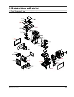
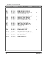
Page 10: ...Samsung Electronics 3 1 3 How to disassemble...

Page 11: ...3 2 Samsung Electronics...

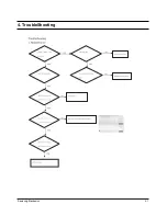
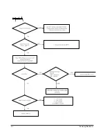
Page 12: ...Samsung Electronics 4 1 4 TroubleShooting...

Page 13: ...4 2 Samsung Electronics...

Page 14: ...xploded Views and Parts List 1 Total Exploded View AD150 AD300 AW120 AC010 HOLD LENS SHEET AC020 AC050 AC070 AC330 TJ1 HEAT AB120 AB130 AL002 AD005 AS260 AH155 AD450 AK420 AL210 AK250 AC320 AK130 MICG...

Page 15: ...B CABINET SIDE L MM DX7 ABS W242 L1 AC070 AH64 04228B CABINET SIDE R MM DX7 ABS W242 L1 AD150 AH64 04223B DECORATION FRONT MM X7 ABS W170 L X AD300 AH64 04232A DECORATION RING MM DX7 ABS X AD450 AH64...

Page 16: ...IC MLC AXIAL 10NF 30 16V Y5S TP FC12R 2202 000797 C CERAMIC MLC AXIAL 10NF 30 16V Y5S TP FC13 2401 000042 C AL 100uF 20 16V GP TP 6 3x7 5 FC1L 2203 000595 C CER CHIP 0 22nF 5 50V C0G 2012 FC1R 2203 00...

Page 17: ...CERAMIC DISC 47nF 80 20 12 5x4m RC15 2201 000161 C CERAMIC DISC 10NF 80 20 500V Y5V TP RC2 2401 001633 C AL 6800uF 20 25V GP BK 18x35 5 7 RC4 2401 001052 C AL 3300uF 20 25V GP 16x31 5 7 RC5 2401 00080...

Page 18: ...00981 R CHIP 5 6Kohm 5 1 8W TP 2012 HR5R 2007 000981 R CHIP 5 6Kohm 5 1 8W TP 2012 HR6L 2007 000338 R CHIP 120Kohm 5 1 8W TP 2012 HR6R 2007 000338 R CHIP 120Kohm 5 1 8W TP 2012 HR8L 2007 000282 R CHIP...

Page 19: ...0501 000341 TR SMALL SIGNAL KSC1623 L NPN 200mW SOT UR1 2007 000290 R CHIP 100ohm 5 1 8W TP 2012 UR101 2007 000468 R CHIP 1Kohm 5 1 8W TP 2012 UR103 2007 000565 R CHIP 220Kohm 5 1 8W TP 2012 UR111 200...

Page 20: ...10 16V X7R 1608 MC36 2203 005148 C CER CHIP 100nF 10 16V X7R 1608 MC37 2203 005148 C CER CHIP 100nF 10 16V X7R 1608 MC38 2203 005148 C CER CHIP 100nF 10 16V X7R 1608 MC39 2203 005148 C CER CHIP 100nF...

Page 21: ...000236 C CER CHIP 0 1nF 5 50V C0G 1608 RC13 2203 000189 C CER CHIP 100nF 80 20 25V Y5V 1608 RC14 2402 001096 C AL SMD 220UF 20 16V GP TP 6 6X6 6X7 RC16 2203 001652 C CER CHIP 470nF 80 20 16V Y5V 1608...

Page 22: ...RR90 2007 000102 R CHIP 100Kohm 5 1 10W TP 1608 RR92 2007 000102 R CHIP 100Kohm 5 1 10W TP 1608 SCREW1 6003 001464 SCREW TAPTITE BH B M3 L10 ZPC WHT TC5 2402 001096 C AL SMD 220UF 20 16V GP TP 6 6X6 6...

Page 23: ...Samsung Electronics 6 1 6 1 Wiring Diagram...

Page 24: ...6 2 Samsung Electronics 6 2 PCB Diagram 1 MAIN FIC1 21PIN CLOCK FIC1 22PIN DATA FIC1 26 27PIN AUDIO SIGNAL...

Page 25: ...Samsung Electronics 6 3 2 FRONT UIC1 15 16PIN 10MHz CRYSTAL UIC1 12 13PIN 32 768KHz CRYSTALS...

Page 26: ...Samsung Electronics 7 1 This Document can not be used without Samsung s authorization 7 1 Block Diagram 1 MAIN Part...

Page 27: ...7 2 Samsung Electronics This Document can not be used without Samsung s authorization 7 2 Schematic Diagram 1 1 MAIN 1 MICOM CLOCK 2 MICOM DATA 3 AUDIO SIGNAL 4 VIDEO SIGNAL...

Page 28: ...Samsung Electronics 7 3 This Document can not be used without Samsung s authorization 4 3 2 1 2 1 FRONT 1 10MHz CRYSTAL 1 32 768KKHz CRYSTAL 3 AUDIO SIGNAL 4 VIDEO SIGNAL...

Page 29: ...Document can not be used without Samsung s authorization 8 1 MAIN MICOM and MPEG MICOM communication MPEG PCB 1 MAIN MICOM TO MAIN MICOM FE 1 U TXD waveform 2 U STB waveform 3 U RXD waveform 4 U ACK...

Page 30: ...8 2 Samsung Electronics This Document can not be used without Samsung s authorization 8 2 Servo MPEG PCB...

Page 31: ...d without Samsung s authorization 8 3 Video output MPPEG PCB VIDEO_Y VIEDO_PB and VIDEO_PR is component video output CVBS1 is composite video output LA73054 is video driver IC 1 CVBS1 waveform 1 VIDEO...

Page 32: ...8 4 Samsung Electronics This Document can not be used without Samsung s authorization 4 PCB IC A SIDE...

Page 33: ...Samsung Electronics 8 5 This Document can not be used without Samsung s authorization B SIDE...

Reviews: