background image

GB

8

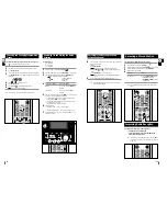
The auxiliary input can be used to take advantage of the
sound quality of your micro-component system when listening
to other sources.

Examples: A 

television

A video disc player

A Hi-Fi stereo video cassette recorder

To connect to the external source, the source must have an
audio output. In addition, you need an RCA connection cable.

Set the system to standby mode and disconnect it and the external
source from the main socket.

Connect the audio cable to the rear of the micro-component system.

Connect the...

To the connector marked...

Red jack............................................... R (right)

White jack............................................. L (left)

For optimum sound quality, do not invert the right and left 
channels.

Plug the system back into the main socket and press Standby/On
(        ) to switch it on.

Select the AUX source by pressing AUX.
Result: 

AUX

is displayed.

Switch the external source on.

Adjust the volume and balance as required:

Volume

Equaliser

Example: You can watch a film and take advantage of stereo sound

provided that the original sound track is in stereo (as if you
were in a cinema).

Connecting to an External Source

1

2

3

4

5

6

Speaker Connection

Directions in Installing Speaker 

Installation in a place near heating apparatus, under direct lay of
light or with high humidity may cause performance degradation of
the speaker.

Do not install on the wall or on a high place of pole or other unsta-
ble place to prevent any safety accident caused by falling of the
speaker.

Do not take the speaker apart from TV or computer monitor. 
The speaker near the TV or computer monitor may influence the
quality of the screen display.

(Right Speaker)

(Left Speaker)

6

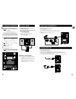
The loudspeaker connector terminals are located on the rear
of the system (red and black tabs).

There are four terminals on the system:

Two for the left speaker (marked L)

Two for the right speaker (marked R)

To achieve the correct sound quality, connect the:

Red wire to the + terminals

Black wire to the - terminals

4

6

GB

9

The AM aerial (for long and medium waves) can be:

Placed on a stable surface

Fixed to the wall (you must first remove the base)

The 

AM

aerial connector terminals are located on the rear of the system and are marked 

AM 

.

To avoid noise interference, check that the loudspeaker wires do not run close to the 
aerial wires.
Always keep them at least 2 inches (5 cm) away.

Connecting the AM (MW)/LW Aerial

How to connect a COAXIAL TYPE aerial.

Connect a 75

antenna to the 

FM

antenna terminal. 

Plug the connector on the 

FM

aerial supplied into the coaxial socket (75

) marked 

FM

on the rear of the system.

Follow the instructions given on 

Page 14

to tune into a radio station, and determine the best position for the aerial.

If reception is poor, you may need to install an outdoor aerial.
To do so, connect an outdoor 

FM

aerial to the 

FM

socket on the rear of the system using a 75

coaxial cable (not supplied).

Connecting the FM Aerial

6

6

4

3

Summary of Contents for MM-ZJ5

Page 1: ...Instruction Manual MICRO COMPONENT SYSTEM MP3 CD CD R RW PLAYBACK MM ZJ5 ...

Page 2: ... AVOID EXPOSURE TO BEAM WARNING TO REDUCE THE RISK OF FIRE OR ELECTRIC SHOCK DO NOT EXPOSE THIS APPLIANCE TO RAIN OR MOIS TURE CAUTION TO PREVENT ELECTRIC SHOCK MATCH WIDE BLADE OF PLUG TO WIDE SLOT FULLY INSERT CAUTION TO REDUCE THE RISK OF ELECTRIC SHOCK DO NOT REMOVE REAR COVER NO USER SERVICEABLE PARTS INSIDE REFER SERVICING TO QUALIFIED SERVICE PERSONNEL RISK OF ELECTRIC SHOCK DO NOT OPEN CAU...

Page 3: ...5 TIMER CLOCK CD MP3 CD TAPE TUNER BAND MO ST TIMER CLOCK TIMERON OFF AUX PROGRAM SET REP A B SLEEP EQ S BASS TAPESPEED REPEAT TUNING MODE VOLUME TUNING ALBUM MUTE 10 POWER SOUND DISPLAY PTY RDS 1 2 3 4 5 6 7 8 9 10 11 12 25 24 23 22 21 20 19 18 17 16 15 14 13 1 TAPE PLAY 2 STANDBY ON 3 MP3 CD CD PLAY PAUSE 4 RECORD PAUSE 5 TUNER BAND 6 AUX 7 SKIP OR SEARCH REWIND 8 HEADPHONE JACK 9 STOP TUNING MO...

Page 4: ...side of the system to ensure good stereo sound Direct the loudspeakers towards the listening area For optimum performance make sure that both speakers are placed at an equal distance above the floor Where to Install Your Micro Component System Connecting your System to the Power Supply Insert or replace remote control batteries when you Purchase the micro component system Find that the remote cont...

Page 5: ...pole or other unsta ble place to prevent any safety accident caused by falling of the speaker Do not take the speaker apart from TV or computer monitor The speaker near the TV or computer monitor may influence the quality of the screen display Right Speaker Left Speaker 6 The loudspeaker connector terminals are located on the rear of the system red and black tabs There are four terminals on the sy...

Page 6: ...the hours Increase the hours When the correct hour is displayed press PROGRAM SET Result The minutes flash To Press Decrease the minutes Increase the minutes When the correct time is displayed press PROGRAM SET Result The clock starts and is displayed even when the system is in standby mode You can display the time even when you are using another function by pressing TIMER CLOCK once 10 Setting th...

Page 7: ...efinitely REPEAT 1 is displayed All songs REPEAT ALL is displayed When you wish to stop the Repeat function press STOP button Result REPEAT is no longer displayed and the function is cancelled Repeating One or All Tracks on the Compact Discs 1 2 CD MP3 CD TUNING MODE REPEAT VOLUME TUNING ALBUM 10 When listening to a compact disc you can quickly search for a specific music passage on a track To sea...

Page 8: ...T REP A B SLEEP EQ S BASS TAPESPEED MUTE 8 8 8 1 BAND 2 3 MO ST 4 14 15 You can check and change your selection of tracks at any time You must have selected at least one track Press STOP once if you have started listening to the selection Press PROGRAM SET Each time you press Program Set the next selection is displayed Press PROGRAM SET one or more times until the track to be changed is displayed ...

Page 9: ...larm Test 1 2 About PS NAME MODE Displays the name of broadcasting station Press the RDS DISPLAY button to select the PS NAME PS NAME appears on the display If the PS information is being received the PS name BBC AFO NDR etc is shown on the display If the PS information isn t received the original FM frequency is shown Even though no RDS DISPLAY button is pressed the reception of PS information en...

Page 10: ...TIMER ON OFF Cancel the timer Once Result is no longer displayed Restart the timer Twice Result is displayed again Timer Function Cancelling the Timer 1 3 4 5 6 7 8 2 CD MP3 CD TAPE TUNER BAND MO ST TIMER CLOCK TIMERON OFF AUX PROGRAM SET REP A B SLEEP EQ S BASS TAPESPEED TUNING MODE REPEAT VOLUME TUNING ALBUM MUTE 10 POWER SOUND DISPLAY PTY RDS 9 1 9 2 3 4 5 6 7 8 4 5 6 7 4 5 6 7 TUNER BAND MO ST...

Page 11: ...EED POWER SOUND DISPLAY PTY RDS To obtain the best possible results from your micro component system you must clean the following elements regularly The outer casing The compact disc player The cassette players heads rollers and drive capstans Always unplug the system from the wall outlet Before cleaning it If you are not going to be using it for a long time Outer Casing Clean the outer casing reg...

Page 12: ...r drive capstans are dirty The tape is worn The TUNER function has not been selected The radio frequency has not been correctly selected The aerial has been disconnected or is not facing the right way Turn it until you find the best orientation You are in a building that blocks radio waves you must use an outside aerial Check that the tape in the cassette is sufficiently taut To prevent erasing a ...

Page 13: ...THIS APPLIANCE IS MANUFACTURED BY AH68 01657B ...

Reviews: