Circuit Description
5-4
Samsung Electronics
DRAM CONTROLLER
As KS32C6100 has DRAM controller, DRAM can be
connected with external memory.
The control mode of DRAM controller can access
EARLY WRITE, NORMAL READ, PAGE MODE, and
BYTE/HALF, and supports EDO DRAM as well as
normal DRAM.
DRAM READ/WRITE signals use /DWE signal to
control system buses. It supports CAS BEFORE RAS
for DRAM REFRESH. Connected with common
/CAS(0-3), /RAS(1:0), it consists of 2 banks and each
may be connected with up to 2M - 8M halfword, the
default setting of this system is 8MB.
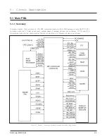
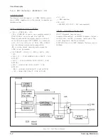
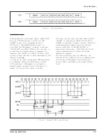
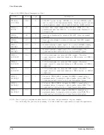
The field of DRAM is in figure 5-1 (Entire Structure of
Main Circuit for Each Key Signal), related timing
diagram is in figure 5-4.
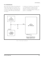
RTC (REAL TIME CLOCK)
RTC circuit maintains current time information, and it
operates in both primary power mode and battery
back-up mode. As RTC does not in MFP controller,
RTC IC is needed separately. This circuit (RTC-4513)
receives clock source from an internal 32.768 kHz
crystal, and divides it into hours, minutes, seconds,
year, month, and day. RTC_EN, DATA and CLK
control the RTC IC. RTC_EN is CHIP SELECT signal,
D ATA is bidirectional signal and used to select mode,
write address, read/write data. CLK reads or output
data in rising edge.
PARALLEL PORT INTERFA C E
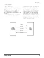
KS32C6100 has parallel port interface enabling
parallel interface with PC. This part connected with
the computer through the centronics connector makes
possible parallel interface with the computer.
I
t
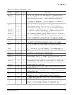
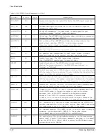
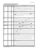
generates control signal and consists of /ERROR, PE,
BUSY, /ACK, SLCT, /INIT, /SLCTIN, /AUTOFD,
and /STB.
Data is transmitted according to the standard of IEEE
P1284 (http://www.fapo.com/ieee 1284.html). The
controller supports compatibility mode which is the
traditional way to transmit print data, nibble mode
(4bit data) to upload data to the computer, and
ECP
(Extended Capabilities Port: 8bit data transmission)
duplex high-speed transmission with the computer.
Compatibility mode, called as Centronics mode, is
protocol which used to transmit data from PC to
printer. ECP mode is protocol which supports rapid
bidirectional communication with input/output
device such as printer, scanner. ECP mode supports 2
cycles for bidirectional communication: Data cycle
and Command cycle. Command cycle is formed run-
length count and channel addressing. RLE (Run
Length Encoding) mode can compress data, and be
used to transmit raster image to printer or scanner.
This system uses RLE method for high-speed
transmission. It enables data to be printed, uploaded,
and downloaded. It also monitors system.
Summary of Contents for MSYS 5150
Page 9: ...2 6 Samsung Electronics Specification Memo ...
Page 16: ...3 26 Samsung Electronics Setup and Installing Memo ...
Page 37: ...4 2 Samsung Electronics Theory of Operation ...
Page 41: ...4 6 Samsung Electronics Memo Theory of Operation ...
Page 116: ...Samsung Electronics 7 9 Maintenance Troubleshooting No Image ...
Page 117: ...Samsung Electronics Maintenance Troubleshooting 7 10 ...
Page 118: ...Samsung Electronics 7 11 Maintenance Troubleshooting All Black ...
Page 119: ...7 12 Samsung Electronics Maintenance Troubleshooting Vertical White Line Band ...
Page 120: ...Samsung Electronics 7 13 Maintenance Troubleshooting Dark Image ...
Page 121: ...7 14 Samsung Electronics Maintenance Troubleshooting Background ...
Page 122: ...Samsung Electronics 7 15 Maintenance Troubleshooting Ghost ...
Page 123: ...7 16 Samsung Electronics Maintenance Troubleshooting Black Dot ...
Page 124: ...Samsung Electronics 7 17 Maintenance Troubleshooting Horizontal Band ...
Page 125: ...7 18 Samsung Electronics Maintenance Troubleshooting Irregular Density ...
Page 126: ...Samsung Electronics 7 19 Maintenance Troubleshooting White Spot ...
Page 127: ...7 20 Samsung Electronics Maintenance Troubleshooting Trembling at the End When OHP Printing ...
Page 128: ...Samsung Electronics 7 21 Maintenance Troubleshooting Poor Fusing Grade ...
Page 132: ...Samsung Electronics 7 25 Maintenance Troubleshooting No Power LCD NO display LED Off ...
Page 133: ...Fuser Error 7 26 Samsung Electronics Maintenance Troubleshooting ...
Page 134: ...Samsung Electronics 7 27 Maintenance Troubleshooting Paper Jam Mis feeding ...
Page 135: ...7 28 Samsung Electronics Maintenance Troubleshooting Paper Jam Jam1 ...
Page 136: ...Samsung Electronics Maintenance Troubleshooting 7 29 Engine Error ...
Page 137: ...7 30 Samsung Electronics Maintenance Troubleshooting Memo ...
Page 187: ...9 28 Samsung Electronics Electrical Parts List ...
Page 189: ...11 Connection Diagram Samsung Electronics 11 1 ...
Page 190: ...12 1 Main Circuit Diagram Samsung Electronics 12 1 12 Schematic Diagrams ...
Page 191: ...Schematic Diagrams 12 2 Samsung Electronics Main Circuit Diagram ...
Page 192: ...Main Circuit Diagram Samsung Electronics 12 3 Schematic Diagrams ...
Page 193: ...Schematic Diagrams 12 4 Samsung Electronics Main Circuit Diagram ...
Page 194: ...Main Circuit Diagram Samsung Electronics 12 5 Schematic Diagrams ...
Page 195: ...Schematic Diagrams 12 6 Samsung Electronics Main Circuit Diagram ...
Page 196: ...Main Circuit Diagram Samsung Electronics 12 7 Schematic Diagrams ...
Page 200: ...12 3 Sensors Circuit Diagram Samsung Electronics 12 11 Schematic Diagrams ...
Page 201: ...Schematic Diagrams 12 12 Samsung Electronics 12 4 Switch Circuit Diagram ...
Page 202: ...Samsung Electronics 12 13 Schematic Diagrams 12 5 Joint Circuit Diagram ...
Page 204: ...Samsung Electronics 12 15 Schematic Diagrams 12 7 PTL Circuit Diagram ...
Page 205: ...Schematic Diagrams 12 16 Samsung Electronics 12 8 SCAN Circuit Diagram ...
Page 206: ...Samsung Electronics 12 17 Schematic Diagrams 12 9 Engin Circuit Diagram ...
Page 207: ...Schematic Diagrams 12 18 Samsung Electronics Engin Circuit Diagram ...
Page 208: ...Samsung Electronics 12 19 Schematic Diagrams 12 10 LIU Circuit Diagram ...
Page 210: ... Samsung Electronics Co Ltd Mar 1999 Printed in Korea P N JC68 00097A Rev 1 00 ELECTRONICS ...


