background image

E-

6

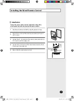
Installing the Wired Remote Control (Continued)

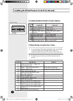
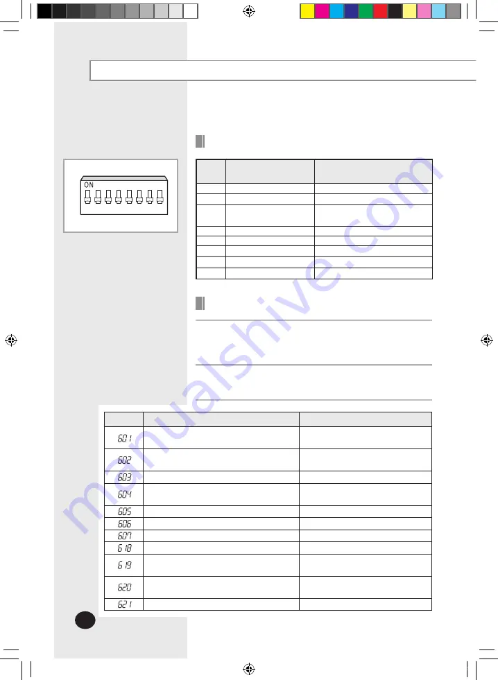
Setting the Wired Remote Control Options

Switch 

No.

Switch OFF

Switch ON

SW1 Cooling and Heating

Cooling Only

SW2 Temp. display : °C

Temp. display : °F

SW3

Allow wireless remote 

control

Disable the wireless remote  

control

SW4 Auto mode enable

Auto mode disable

SW5 Mode lock enable

Mode lock disable

SW6

-

-

SW7

-

-

SW8 Main remote control

Sub remote control

1

SW1 SW2

DIP 601

SW3 SW4 SW5 SW6 SW7 SW8

2 3 4   5 6 7 8

 

Default setting

Wired Remote Control Error Codes

1

The error codes of the indoor and outdoor units are displayed 

on the wired remote control. Refer to the indoor and  

outdoor unit technical manuals for the error codes reference.

2

The following error codes are related to the wired remote  

control.

Display

Explanation

Remark

Wired remote control 

 Indoor unit  

communication error

-

Main 

 Sub wired remote control  

communication error

When using 2 wired remote  

controls to control one indoor unit.

Communication packet error 

-

Wired remote control tracking error 

No indoor units found

-

7 Day scheduler error 

-

COM1/COM2 installation error

-

COM2 dual main error 

-

Excessive indoor unit installation error

-

Temperature units (Celsius/Fahrenheit) 

mixed setting error of installed indoor units

-

Temperature units (Celsius/Fahrenheit)  

setting error

-

Main/Sub DIP option setting error

-

DB98-28133A-05_IM_SIMPLE Wired Remote_EU_EN_.indd   6

2020-09-28   오후 1:42:34

Summary of Contents for MWR-SH00

Page 1: ...te Control MWR SH00 Thank you forpurchasing this Samsung Product Before operating this unit please read this installation manual carefully and retain it for future reference DB98 28133A 05_IM_SIMPLE W...

Page 2: ...n authorized installation center WARNING CAUTION Do not use inflammable gases near the wired remote control Do not install the wired remote control in a location where it will come into contact with c...

Page 3: ...Error Codes 6 Connecting theWired Remote Control 7 Note The illustrations will help you to understand the symbols displayed in the pictures The illustrations in the step by step procedures use 3 diffe...

Page 4: ...the power cable to avoid malfunction of the unit Connecting the power cable to the communication terminal of the wired remote control will cause serious damage to the wired remote control Make sure th...

Page 5: ...he rear cover of the wired remote control to the wall with 2 screws 3 Connect the V1 V2 terminal of the wired remote control to the V1 V2 terminal of the indoor unit 4 Connect the F3 F4 terminal of th...

Page 6: ...Refer to the indoor and outdoor unit technical manuals for the error codes reference 2 The following error codes are related to the wired remote control Display Explanation Remark Wired remote control...

Page 7: ...ol Using one wired remote control for one indoor unit Note The wired remote control can be only installed on COM2 Outdoor unit Indoor unit COM1 COM2 COM1 COM2 COM2 Wired remote control DB98 28133A 05_...

Page 8: ...its may be controlled as a group Group Control Using one wired remote control for a group of indoor units Outdoor unit Indoor unit COM1 COM1 Wired remote control COM2 COM2 COM1 Outdoor unit Indoor uni...

Page 9: ...ingle indoor unit or a group of indoor units 1 SW1SW2SW3SW4SW5SW6SW7SW8 2 3 4 5 6 7 8 1 SW1SW2SW3SW4SW5SW6SW7SW8 2 3 4 5 6 7 8 Outdoor unit Indoor unit COM1 Wired remote control Main COM2 Wired remote...

Page 10: ...E 10 MEMO DB98 28133A 05_IM_SIMPLE Wired Remote_EU_EN_ indd 10 2020 09 28 1 42 34...

Page 11: ...E 11 DB98 28133A 05_IM_SIMPLE Wired Remote_EU_EN_ indd 11 2020 09 28 1 42 34...

Page 12: ...DB98 28133A 05 DB98 28133A 05_IM_SIMPLE Wired Remote_EU_EN_ indd 12 2020 09 28 1 42 34...

Reviews: