background image

E-

28

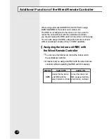
When using automatic ADDRESS of DVM PLUS, assign 
MAIN ADDRESS to the indoor and outdoor unit. 
The RMC is not assigned to the indoor unit. If you want to
control the air conditioner with the centralized controller, 
you should operate the RMC switch of the indoor unit manually. 
You can also assign the RMC using wired remote controller
without operating manually. (Only in COM2 available)

You can use this function to control the indoor unit in
the centralized controller.

It means that you assign the RMC with the wired remote
controller without operating the RMC switch manually.

Assigning the indoor unit RMC with
the Wired Remote Controller

S/W NO.

SW5

Switch OFF

Assign the the indoor
unit RMC with the
wired remote controller

Switch ON

Cancel the indoor unit
RMC assigned with the
wired remote controller

Additional Function of the Wired Remote Controller

Summary of Contents for MWR-TH00

Page 1: ...NUAL DE INSTALAÇÃO INSTALLATIONS HANDBUCH E XEIPI IO E KATA TA H àçëíêìäñàü èé ìëíÄçéÇäÖ System Air Conditioner Aire acondicionado sistemático Climatiseur numérique multifonctionnel Sistema Aria Condizionata Sistema Ar Condicionado Klimaanlage System ÛÙËÌ ÏÈÌ ÙÈÛÌÔ ëËÒÚÂÏÌ È ÇÓÁ Û Ì È äÓÌ ËˆËÓÌ ENGLISH ESPAÑOL FRANÇAIS ITALIANO PORTUGUÊS DEUTSCH E HNIKA RUSSIAN ...

Page 2: ...ult authorized installation center WARNING CAUTION Do not use inflammable gases near the remote controller Do not install the remote controller in a location where it will come into contact with the combustible gases machine oil sulphide gas etc Avoid a location where acid alkali solution or special spray is used Choose a location that is dry and sunny but not exposed to direct sunlight Available ...

Page 3: ...ors indicated on the Wired Remote Controller 12 I I I IN N N NS S S ST T T TA A A AL L L LL L L LI I I IN N N NG G G G T T T TO O O O C C C CO O O OM M M M2 2 2 2 F F F F3 3 3 3 F F F F4 4 4 4 INSTALLING THE COMMUNICATION CABLE Installing the Communication cable 13 Installation 14 Setting up indoor unit PCB and Wired Remote Controller Option Switches 15 The errors indicated on the Wired Remote Con...

Page 4: ...ler check that you have turned off the main power All cables should be installed according to the national wiring rules and you must install it to the wall not to be touched by users Communication cable and power cable should be installed separately Connecting the power cable to communication terminal will cause serious damage to the wired remote controller Please make sure that the power cable is...

Page 5: ...OM1 Assign the DS01 switch of the PCB of the wired remote controller to SW2 ON Install the wired remote controller to COM2 Assign the DS01 switch of the PCB of the wired remote controller to SW2 OFF Flowchart for dividing COM1 COM2 PCB of the indoor unit Wired remote controller PCB K1 Adjust to OFF position S W NO SW2 Switch ON COM1 F1 F2 Switch OFF COM2 F3 F4 ...

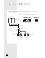
Page 6: ...f COM1 COM2 COM1 Diagram MAIN RMC MAIN RMC MAIN RMC DVM Outdoor unit COM1 F1 F2 Group control Wired remote controller Indoor unit COM2 Diagram DVM PLUS Outdoor unit COM1 F1 F2 COM2 F3 F4 COM2 F3 F4 Group control Wired remote controller Indoor unit ...

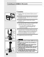
Page 7: ...s shown in the picture The wired remote controller power cable is installed in all air conditioners except 1 way cassette AC Power supply Don t confuse the color Red Blue White Black Red Blue White Black Power cable of the wired remote controller Communication cable of the wired remote controller COM1 F1 F2 Red2P 2 5 pitch Red2P 2 5 pitch Indoor unit PCB White2P 2 5 pitch White2P 2 5 pitch Install...

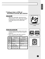
Page 8: ...door unit PCB to ON 4 If you set to COM2 and install it to COM1 606 of error signs is displayed on the wired remote controller DS01 SW1 SW2 SW3 SW4 SW5 SW6 SW7 SW8 DS02 SW1 SW2 SW3 SW4 SW5 Cooling Only COM2 F3 F4 C The wired and wireless remote controller available Cooling and Heating COM1 F1 F2 F Can be used wired remote controller only Switch No Switch OFF Switch ON Refer to the chapter Addition...

Page 9: ... unit as shown in the picture can control it with the wired remote controller ADDRESS of the wired remote controller and RMC ADDRESS of the indoor unit should be assigned as the same Therefore as the RMC ADDRESS is adjusted to 0 in the picture the indoor unit is controlled by the wired remote controller which is adjusted to 0 Assign the RMC ADDRESS of the wired remote controller same as the indoor...

Page 10: ...S RCM ADDRESS SW4 MAIN RMC MAIN RMC MAIN RMC DVM Outdoor unit Wired remote controller Indoor unit PCB Indoor unit Individual control Individual control of 3 indoor units with 3 wired remote controller Examples of installing Wired Remote Controller ...

Page 11: ...DDRESS 0 of the wired remote controller individually and controlling the other 2 indoor units with ADDRESS 1 of the wired remote controller as a group MAIN ADDRESS RCM ADDRESS SW4 Indoor unit PCB DVM Outdoor unit MAIN RMC MAIN RMC MAIN RMC Wired remote controller Indoor unit Group control ...

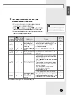
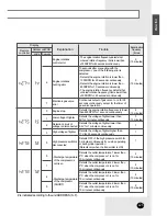
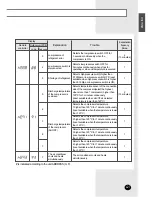
Page 12: ...IN sensor separation error of the indoor unit EVE OUT sensor separation error of the indoor unit Open error of electronic expansion valve in the outdoor unit Close error of electronic expansion valve in the outdoor unit EVE MID EVE OUT sensor simultaneous separation error of the indoor unit SUB COOL sensor separation error of the outdoor unit Refrigerant leak of outdoor unit Loading Failure COND M...

Page 13: ...lor Red Blue White Black Red Blue White Black Power cable of the wired remote controller Communication cable of the wired remote controller COM2 F3 F4 White 2P 2 5 pitch Blue 2P 2 5 pitch White 2P 2 5 pitch Indoor unit PCB Blue 2P 2 5 pitch F3 F4 Connector type cable connection AC Power supply Don t confuse the color Red Blue White Black Red Blue White Black Power cable of the wired remote control...

Page 14: ... error sign is displayed on the wired remote controller C C C CA A A AU U U UT T T TI I I IO O O ON N N N Install the wired remote controller of GHP in the same way The wired remote controller must be installed by an installation specialist Before installing the wired remote controller check that you have turned off the main power All cables should be installed according to the national wiring rul...

Page 15: ...he wired remote controller with the indoor unit to be controlled You don t have to assign the ADDRESS Refer to the following option table to assign the switch according to the user s situation SW1 SW2 SW3 SW4 SW5 Cooling Only COM2 F3 F4 C Wired and wireless remote controller available Cooling and Heating COM1 F1 F2 F Can be used wired remote controller only Switch No Switch OFF Switch ON Refer to ...

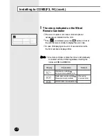
Page 16: ...al indoor units the front number is displayed first The errors indicated on the Wired Remote Controller N N N No o o ot t t te e e e 2 remote controller controls the indoor unit individually connected with the COM2 regardless of setting the indoor unit RMC ADDRESS Master wired remote controller Slave wired remote controller COM1 COM2 cross installed error Wired remote controller Indoor unit commun...

Page 17: ... N N N No o o ot t t te e e e Don t change the DS03 switch of wired remote controller PCB from the default settings when the outdoor unit is shipped from the factory If you change the default settings the communication error is displayed and the wired remote control doesn t operate normally The wired remote controller controls the indoor unit individually connected with the COM2 regardless of the ...

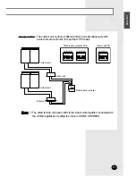
Page 18: ...to COM2 F3 F4 cont Wired remote controller PCB Indoor unit PCB Outdoor unit Wired remote controller Indoor unit COM2 COM2 COM1 COM1 COM1 Group control Controlling more than 2 indoor units with a wired remote controller ...

Page 19: ...controller Except the GHP model Outdoor unit Outdoor unit Wired remote controller Indoor unit Indoor unit Wired remote controller PCB Indoor unit PCB The wired remote controller controls the indoor units together connected with the COM2 regardless of setting the indoor unit RMC ADDRESS N N N No o o ot t t te e e e ...

Page 20: ...ol 1 indoor unit Outdoor unit Indoor unit Wired remote controller PCB Indoor unit PCB COM2 COM1 DS03 DS03 Wired remote controller Master Set to 0 Set to 1 Wired remote controller Slave Set the DS03 switch of the wired remote controller PCB as shown in the picture Installing to COM2 F3 F4 cont ...

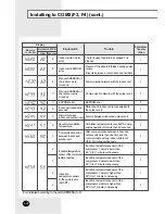
Page 21: ...e than once and cut off for 2 minutes continuously 1 1 1 1 1 1 1 Indoor and outdoor unit connection error Indoor and outdoor unit communication error Communication error between the indoor unit and centralized controller After communication between the wired remote controller and indoor unit more than once and communication cuts off for 2 minutes continuously Communication error between the wired ...

Page 22: ...utdoor unit is mixed up Indoor unit connection exceeds Discord between indoor and outdoor unit Abnormal ventilation temperature Communication error between indoor and outdoor unit Induction temperature sensor of the compressor is disconnected Induction temperature sensor of the compressor SHORT Induction temperature sensor of the compressor 1 detects lower than 39 C for 1 minute continuously Induc...

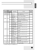
Page 23: ...let temperature sensor 2 is disconnected Accumulator outlet temperature sensor 1 SHORT Accumulator outlet temperature sensor 2 SHORT Accumulator outlet temperature sensor 1 is safe Accumulator outlet temperature sensor is safe Outdoor heat exchanger temperature sensor is disconnected Outdoor heat exchanger temperature sensor SHORT Engine water temperature sensor is disconnected Accumulator outlet ...

Page 24: ... seconds when the high pressure lower than 0 1Mpa when the compressor turns on Detects high pressure lower than 0 1Mpa when operating of next term After turning the starter on rotation pulse is less than 24 Detects the engine rotation is lower than 1000RPM for 60 seconds continuously Detects the engine rotation is lower than 800RPM for 10 seconds continuously 15 seconds after connecting with the c...

Page 25: ... the compressor 3 is on for 10 minutes continuously Detects the outlet temperature 4 lower than 5 C when the compressor 4 is on for 10 minutes continuously Detects the voltage of lighter lower than 0 5V for 1 minute continuously Detects the voltage of lighter higher than 17V for 30 seconds continuously Detects OFF of the high pressure switch for 3 minutes continuously if you stop operating or duri...

Page 26: ...ure higher than 2 9Mpa for 5 seconds continuously when the compressor is ON Detects when the compressor is turned ON the higher temperature from the temperature range that the inlet sensor sensed in the connection parts of the compressor over 60 C for 10 minutes continuously 1 Detects the engine water temperature for operating higher than 105 C for 10 seconds continuously reset lower than 90 C ava...

Page 27: ...er than 120 C for 1 minute continuously reset available when the temperature is lower than 120 C Detects the compressor temperature 4 higher than 120 C for 1 minute continuously reset available when the temperature is lower than 120 C The air conditioner cools and heats simultaneously 2 Detects low pressure switch OFF for 3 minutes continuously when stops for operating or when oil temperature is s...

Page 28: ...ntroller without operating manually Only in COM2 available You can use this function to control the indoor unit in the centralized controller It means that you assign the RMC with the wired remote controller without operating the RMC switch manually Assigning the indoor unit RMC with the Wired Remote Controller S W NO SW5 Switch OFF Assign the the indoor unit RMC with the wired remote controller S...

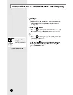
Page 29: ...it Main ADDRESS display Set SW5 of DS02 switch on the wired remote controller PCB to OFF 1 Press the button and button in front of the wired remote control simultaneously for more than 5 seconds 2 Wired remote controller LCD displays as shown in the picture and changes to the Indoor unit group ADDRESS setting mode 3 Set the indoor unit PCB ...

Page 30: ...in to quit the setting mode and enter the operation mode C C C CA A A AU U U UT T T TI I I IO O O ON N N N When assigning the RMC the wired remote controller of each indoor unit should be installed one to one If you assign the RMC to the indoor unit with the wired remote controller the indoor unit is controlled by the RMC assigned with the wired remote controller in the centralized controller even...

Page 31: ...on and button in front of the wired remote controller simultaneously for more than 5 seconds 2 Wired remote controller LCD displays as shown in the picture and changes to the Indoor unit group ADDRESS setting mode 3 SW1SW2SW3SW4 SW5SW6SW7SW8 Wired remote controller PCB DS01 DS02 Wired remote controller LCD Group ADDRESS RMC display Indoor unit Main ADDRESS display ...

Page 32: ...ESS with the beep sound Press the button again to quit the setting mode and enter the operation mode Example of the display Wired remote controller LCD If you set the PCB RMC switch to 3 Additional Function of the Wired Remote Controller cont If you press the button in the mode except the Setting the RMC switch quit the Canceling the group ADDRESS mode Initial display Setting the RMC switch Quit ...

Page 33: ...E 33 ENGLISH Memo ...
Page 34: ...NADO HA SIDO FABRICADO POR CE CLIMATISEUR EST FABRIQUE PAR QUESTO CONDIZIONATORE D ARIA È PRODOTTO DA ESTE APARELHO DE AR CONDICIONADO É FABRICADO POR DIESE KLIMAANLAGE IST FABRIZIERT VON AYTH H Y KEYH KATA KEYA THKE A O ùíéí äéçÑàñàéçÖê àáÉéíéÇãÖç îàêåéâ Printed in Korea ...

Reviews: