background image

This Service Manual is a property of Samsung Electronics Co., Ltd.

Any unauthorized use of Manual can be punished under applicable

International and/or domestic law.

© Samsung Electronics Co., Ltd. Dec. 2010.   

  Printed in Korea.

  Code No. DB98-33320A(1)

GSPN(Global Service Partner Network)

Area

Web Site

North America

http://service.samsungportal.com

Latin America

http://latin.samsungportal.com

CIS

http://cis.samsungportal.com

Europe

http://europe.samsungportal.com

China

http://china.samsungportal.com

Asia

http://asia.samsungportal.com

Mideast & Africa

http://mea.samsungportal.com

유선리모컨_MWR-WE10_E_33320A(1)_co.indd   2

2010-12-23   오후 5:50:29

Summary of Contents for MWR-WE10

Page 1: ...tion WIRED REMOTE CONTROL CONTENTS WiredRemoteControl Basic MWR WE00 Model MWR WE10 Model Code MWR WE10 1 Precautions 2 Product Specifications 3 Disassembly and Reassembly 4 Troubleshooting 5 ExplodedViews and Parts List 6 PCB Diagram 7 Wiring Diagram 8 Schematic Diagram MWR WE10 ...

Page 2: ... 2 13 2 4 2 Tracking Your Indoor Unit from the Wired Remote Controller 2 15 2 5 Optional Materials Specifications 2 16 2 5 1 Accessories 2 16 3 Disassembly and Reassembly 3 1 4 Troubleshooting 4 1 4 1 Checklist before Diagnosis 4 1 4 1 1 Wired Remote Control Error Codes 4 1 4 1 2 Wired Remote Control Error List 4 2 4 2 Troubleshooting by Condition 4 3 4 2 1 LCD Display Does Not Appear 4 3 4 2 2 Co...

Page 3: ...h as tracking and short Check the assembly status of parts after repairing the break down It should be same as the status before repairing Do not pull any electric wires and do not touch an auxiliary power switch with a wet hand There is a danger of electric shock or fire In case any wire or power plug has been damaged replace it to eliminate any possible danger Do not bend the power cord by force...

Page 4: ...hat detect human presence automatic cleaning and S Plasma ion etc ERV PLUS AHU Humidification supply of outside air and clean up etc Integrated control between systems is necessary due to the growth in the market for ventilation products Remote control integrated between the air conditioner and ERV products is necessary Energy saving is realized through interlocking control 1 PBA Main PBA SAMSUING...

Page 5: ...w Display Application of display communicating IC to expand the segment Separate development of LCD PBA including backlight Other 1 Development of new inlay 2 Review of new labels Option Door and Box 3 New User Installation Service manuals 4 Application of display communicating method with the application of display IC 5 Compatibility of newly developed set Global 4Way ERV Plus and AHU etc 6 New a...

Page 6: ...ndensation Power 1 Input 12VDC 500mA Installation 2 Installation space Installing on the wall using the exclusive install bracket Delivery 1 Opening Conform to the appointed order 2 Confirmation of delivery Confirm with the delivery check sheet and repair faulty items Follow the method usage conditions and notices according to the user guide When a problem occurs during this process it supported b...

Page 7: ...velopment Specifications Display Operation On Off button LED Indicator Green Normal Red Need to be checked Temperature Setting Button Without opening the cover of yourWired Remote Controller you can turn the air conditioner power On Off or set the desired temperature ...

Page 8: ...ng displays Displays Current day or scheduled day _ Displays Schedule number Displays Scheduled device selection Displays Current time summer time scheduled time Ventilator ERV related information Displays Ventilator ERV operation Displays Clean up Displays Ventilator ERV fan speed Commom function related information Displays Invalid operation Filter cleaning filter cleaning period Displays Dust b...

Page 9: ...the air conditioner power On Off Mode button Selects the desired air conditioner operation Temperature setting button Sets the desired temperature Fan speed button Changes the air conditioner s fan speed Air Swing button Changes the air flow direction to move upward or downward Temp button Checks the indoor temperature Quiet Sleep button Selects Quiet or Sleep operation for the air conditioner ...

Page 10: ...etween items or change the item value Set button Save your new settings ESC button Return to general mode from schedule and detailed setting screens Delete button Cancel the schedule setting Auto Clean button Use the auto cleaning function for your air conditioner CO2 kWh button Display the amount of CO2 and the power consumption Filter Reset button Turn off the filter cleaning displays filter usi...

Page 11: ... the data setting screen Once you have entered the setting screen the current setting will be displayed Refer to the chart for data setting Using the buttons change the settings and press the button to move to the next setting Press the Set button to save the setting and exit to the sub menu setting screen Press the Esc button to exit to general mode Functional Development Specifications cont Deta...

Page 12: ...tTime Setting Day Hour Minute Day AM PM 1 2 3 4 Friday PM 12 00 Sun Sat AM PM 0 12 0 59 Day hour minute 5 1 SummerTime Use and Setting Methods Use of summer time Y N 1 0 0 No use 1 Use Summer Time Application Method 2 0 0 Weekly 1 Daily 2 Summer time use Weekly Start Month th Sunday 1 2 4 03 F 1 12th month 1 4 F last week th week 3 Summer time use Weekly End Month th Sunday 1 2 4 10 F 1 12 month 1...

Page 13: ...screen Using the buttons select a sub menu number and press the button to enter data setting screen When you enter the setting stage the current setting will be displayed Refer to the chart for data settings Using the buttons select the settings Press the button to move to the next setting Press the Set button to save the settings and exit to the sub menu setting screen Press the Esc button to exi...

Page 14: ...lock 1 lock LockofBlade4 4 0 0 Unlock 1 lock 4 ERVoption Setting checking UseofBy Passmode 1 0 0 Nouse 1 Use UseofAutomode 2 0 0 Nouse 1 Use Useofairpurificationmode 3 0 0 Nouse 1 Use Useofexternalcontrol 4 0 0 Nouse 1 Use 5 RoomTemperaturecompensation Temperaturecontrolreference 1 2 3 0 9 40 C 0 1 C Temperaturecompensationvalue 4 5 6 0 9 9 9 9 C 0 1 C 6 Numberofconnectedunits Numberofindoorunits ...

Page 15: ...umidificationwhenHeating 4 0 Nouse 1 Use 2 ERVPlustemperature setting checking Cooling 1 2 15 30 C 1 C Heating 3 4 15 30 C 1 C 3 ERVPlusAutomodetemperaturesetting checking Settemperature 1 2 15 30 C 1 C Settemperaturedifference 3 4 5 15 C 1 C 4 Setting checkingthecompensatingtemperatureAundertheHeating EEVcontrolforERVPlus 1 2 0 10 C 1 C CheckingthecompensatingtemperatureBundertheHeating EEVcontro...

Page 16: ...e two hooks at the bottom of your Wired Remote Controller at the same time and then pull up the front cover to separate it from the rear cover Push the two hooks at the same time Insert a flat head screwdriver into the square groove in the upper area of the hook to disassemble it easily When the cable is not concealed When the cable is concealed 15cm 10cm If you need more space for the wiring work...

Page 17: ...e 30cm of the sheath of the cable and install it only with the four pieces of wires Recommended specification AWG21 The following are the specs of the compression ring terminal connected to yourWired Remote Controller PCB Screws on the PCB terminal must be tightened with less than 6N cm tightening torque If the tightening torque is greater it may damage the screw thread Align the controller with t...

Page 18: ...ive seconds The system will reset and tracking will start again 3 During tracking the total number of currently searched indoor units and ventilator ERV will be displayed If you want to perform tracking again after installation then press the Esc and Delete buttons at the same time for more than five seconds Only the masterWired Remote Controller can display the total number of indoor units and ve...

Page 19: ...emark Wired remote control DB93 11251B 1 Cable tie DB65 10099B 2 Cable clamp DB65 10074E 3 Cable clamp 6002 000474 5 User Manual DB98 32810A 1 Installation Manual DB98 32811A 1 U terminal DB60 00444A 6 2 5 Optional Materials Specifications 2 5 1 Accessories ...

Page 20: ...MEMO Samsung Electronics 2 17 ...

Page 21: ...ad screwdriver When assembling assemble the upper part first as in the picture and then insert the bottom hook 2 Separate the door cover by pushing the bottom right part of the product sideways For assembling or dismantling leave the door cover open about 130 degrees as in the image to do the work Otherwise the hinge may be incorrectly assembled resulting in faulty operation 3 Disassembly and Reas...

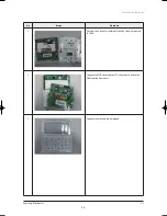
Page 22: ...y and Reassembly 3 2 No Image Procedure 3 Unscrew the 6 screws assembled in the front cover to separate the PBA 4 Separate the PCB cover and the LCD connector to detach the PBA from the front cover 5 Separate the attached rubber keypad ...

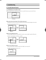
Page 23: ...d one after another Example 121 error occurred in No 28 ventilation system ERV Ventilation system ERV LCD Display 4 Troubleshooting 4 1 Checklist before Diagnosis 4 1 1 Wired Remote Control Error Codes The error codes of the wired remote control and the products connected to the remote are shown on the LCD display Errors Found in Indoor Unit Outdoor Unit Product Group Indication A The product addr...

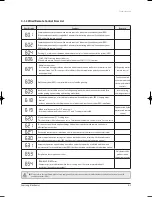
Page 24: ...ide gear control Exceeded maximum no of installation for indoor unit ventilation system ERV 16 equipment devices A reset is required after checking the number of indoor unit ventilation system ERV installations Mixed installation error for C F indoor unit Error occurs when mixed indoor units of C and F settings are installed Only detected by the master wired remote control Wired remote control C F...

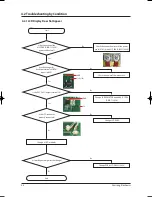
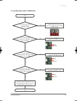
Page 25: ... PBA DB93 11243A power cable normal Are the voltages for both the terminals of BD01 input side12V Is the IC03 7805 output terminal 5V Check the connection status of the power cable V1 V2 with ASS Y PBA DB93 11243A No Change of LCD modules End Yes Yes GND GND 12V 12V 5V Is the LCD connector properly connected Is it working normally after the change 4 2 Troubleshooting by Condition 4 2 1 LCD Display...

Page 26: ...resistance between the upper part of ASS Y PBA DB93 11243A C302 and GND at least 100KΩ Change ASS Y PBA DB93 11243A No Yes Is the resistance between the lower part of ASS Y PBA DB93 11243A C302 and GND at least 100KΩ Change ASS Y PBA DB93 11243A No End Check the communication of the indoor unit connected to wired remote control this is not a problem with the wired remote control GND GND GND 100KΩ ...

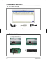
Page 27: ...232 Cable Upgrade Kit switch SW 3 4 OFF SW 1 2 Don t care SW 1 2 OFF Indise switch State SW 1 position OFF SW 2 position ON If switch setting is wrong then upgrading fails 4 3 How to Download Micom Software 4 3 1 Micom Software Upgrade Kit 4 3 2 Upgrade Kit Switch setting ...

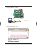
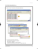
Page 28: ...ram 1 3 2 USB RS232 Cable Power Cable 10 pin flat cable Select a COM port and set the Baud rate at 115200bps Select Indoor Select the Micom software to download by pressing the Select File button Start downloading by pressing the Download button 2 3 5 4 1 Only SoC software version from Mar 14 2008 or later can be used 2 Can t be upgraded with empty software in the Soc ...

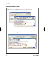
Page 29: ...eshooting Micom Software Upgrading Order cont 3 The download is successful if the Successful message appears with the upgrade status 4 If the Download has failed message appears then check the connection status and start again 1 1 2 ...

Page 30: ...ars 6 Troubleshooting and Solution for Other Problems Bootloader of SOC Micom is damaged Change PCB PBA is damaged Change PBA Problem found in the upgrade kit Change the upgrade kit Problem found in a cable USB Power 10 pin flat cable Change the relevant cable Check if the connection is normal by pressing the Check Connection button 1 2 2 1 ...

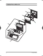
Page 31: ...5 1 Samsung Electronics 1 5 3 7 2 6 4 1 4 1 1 1 6 1 7 1 2 1 3 1 5 4 1 5 3 1 5 2 1 5 1 5 5 1 5 1 5 Exploded Views and Parts List ...

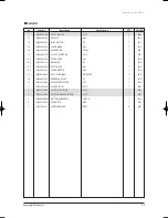
Page 32: ... DB61 04671A GUIDE LED PC 1 SNA 1 5 3 DB64 02600A BUTTON KEY ABS 1 SNA 1 5 4 DB63 02840A COVER BUTTON ABS 1 SNA 1 5 5 DB98 33083A ASS Y DOOR LABEL ART PAPER 1 SNA 1 6 DB64 02599A WINDOW DISPLAY PC 1 SNA 1 7 DB02 00044A TAPE ETC PROTECTOR PET 1 SNA 2 DB61 04652A CASE BOTTOM ASS Y 1 SA 3 DB93 11266B ASS Y DISPLAY WE10 ASS Y 1 SA 4 DB93 11243A ASS Y PCB MAIN SOLUTION ASS Y 1 SA 5 DB64 02608B BUTTON R...

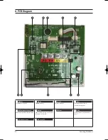
Page 33: ...n of communication power 485 Communication with indoor unit Supply of power in the case of power suspension for Clock IC In charge of non polar function for power MICOM FRAM Clock IC Relay 485 Communication part Battery 5V Power Doide Temperature sensor LCD Control IC 10 2 1 4 5 8 9 7 6 3 6 PCB Diagram ...

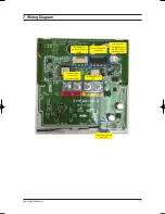
Page 34: ...elopment download connector ASPRO Communication connector 485 communication Power connector 12V Service download connector LCD connector backlight power and LCD data I2C communication Temperature sensor connector 7 Wiring Diagram ...

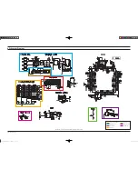
Page 35: ...nication Download Part Switch Part Reset IC Part Temp Sensor Part EEPROM Part 8 Schematic Diagram This Document can not be used without Samsung s authorization Samsung Electronics 유선리모컨_MWR WE10_E_33320A 1 _1 indd 1 2 2010 12 23 오후 5 52 ...

Page 36: ...ronics Co Ltd Dec 2010 Printed in Korea Code No DB98 33320A 1 GSPN Global Service Partner Network Area Web Site North America http service samsungportal com Latin America http latin samsungportal com CIS http cis samsungportal com Europe http europe samsungportal com China http china samsungportal com Asia http asia samsungportal com Mideast Africa http mea samsungportal com ...

Reviews: