background image

1. Cautions

2.  Features and Specifications

3.  Disassembly and assembly

4. Troubleshooting

5.  Parts layout

6.  Wiring diagram

7.  S/W Download

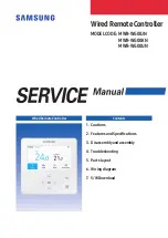
Wired Remote Controller

Contents

Wired Remote Controller

MODEL CODE :  MWR-WG00JN 

MWR-WG00KN 

MWR-WG00UN

Summary of Contents for MWR-WG00JN

Page 1: ...Features and Specifications 3 Disassemblyand assembly 4 Troubleshooting 5 Parts layout 6 Wiring diagram 7 S WDownload WiredRemoteController Contents Wired Remote Controller MODELCODE MWR WG00JN MWR WG00KN MWR WG00UN ...

Page 2: ...duct Specification 2 6 2 3 1 Environment and Specification 2 6 2 3 2 Feature expansion specification 2 7 2 4 How to install 2 22 2 4 1 Wired remote control installation 2 22 3 Disassembly and assembly 3 1 4 Troubleshooting 4 1 4 1 Things to check before diagnosis 4 1 4 1 1 Errors displayed on the Wired Remote Controller 4 1 4 2 Action by symptom 4 2 4 2 1 When the LCD screen does not come out 4 2 ...

Page 3: ...vent fire hazard such as TRACKING SHORT Check the assembly of the parts after the fault has been repaired It must be in the same state as before repair 1 2 Product Safety Precautions Do not pull on the wire or touch the power plug or the auxiliary power switch with wet hands Risk of electric shock or fire If the power cord or power plug is damaged be sure to replace it to prevent danger Do not ben...

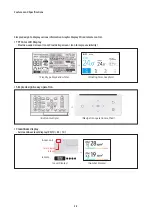
Page 4: ...s Color Graphic LCD 4 3 wired remote control with large screen Floating Display for user desired point function Connect up to two wired remote controls It can be controlled in one group Master Slave Wired remote control indoor unit ERV Connect up to 16 units into one group It is controllable Master Slave ...

Page 5: ...lay Provide needed screen Icon Provide big screen Icon to improve visibility Fixed type black and white Floating Color Graphics Simple design easy operation Button multiple Navigation operation method Cleanliness display Air cleanliness level display PM 10 2 5 1 0 Color display Step 4 Indoor unit remote Level display Number display ...

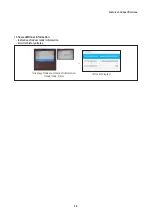
Page 6: ...Features and Specifications 2 3 Show additional information Indication of indoor model information Error list history display Display of indoor unit model information model code S No Error list display ...

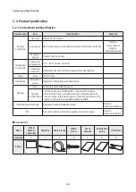
Page 7: ...ftware code Main Micom DB91 01954A Fixed Display Icon No air cleanliness indication No indication of indoor model information Software code Main Micom DB91 02147A DB91 02147A DB91 02147A Touch Micom DB91 02076A DB91 02076A DB91 02076A Image Micom DB91 02077B DB91 02077C DB91 02077B Color Floating Display Icon Air cleanliness value display PM 10 2 5 1 0 Indication of indoor model information Serial...

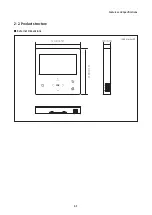
Page 8: ...Features and Specifications 2 5 2 2 Product structure External Dimensions 120 0 4 72 19 0 0 75 120 0 4 72 Unit mm inch ...

Page 9: ...2VDC 25A Installation Installation space Installation Mounting wall Installation Delivery Open Follow the prescribed sequence Delivery confirmation Check by delivery CHECK SHEET repairdefective items Instructions foruse conditions of use and precautions for use are given in the instructions In case of a problem in this process the service is available where possible Installation Instructions Refer...

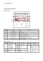
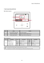
Page 10: ...t of the temperature of the up and down orfunction setting value Left and Right button change of the function setting value OK Button Save the setting value Return aftersave button Save the setting value and moving back to the previous step Setup button Select of setup function Some functions may not work according to indoor unit specifications The LED indicator shows the operating status of the p...

Page 11: ...Auto Turbo High Medium Low Wind Free mode Wind Free On Off Only if the indoorunit has this function Airflow direction mode Fix Swing Individual Icon Description Icon Description Icon Description Icon Description Reservation When a General Schedule is set When a Setback Schedule is set Lock indication Discharge temperature FilterReset Activation Time Setting display When Energy Saving Timeris activ...

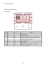
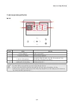
Page 12: ... out Wind strength indicator Auto Turbo Strong and Weak winds Icon Description Icon Description Icon Description Icon Description Reservation When a General Schedule is set When a Setback Schedule is set Central Control FilterReset Check Defrost Lock indication Kitchen Hood Functions that are not supported are marked inactive and can not be set If the button is not pressed for 7 seconds the functi...

Page 13: ...um Name Function Quiet Quiet mode On Off Sleep Sleep mode On Off Long wind Long wind On Off only if the indoorunit has this function Schedule General Setback Schedule Override Energy Saving Timer Eco Setting Activation Time Setting Purify Purity mode On Off AirQuality AirQuality On Off Option Additional function such as general errorlist and so on Energy Energy Usage Energy Setting ...

Page 14: ...etback Schedule Override Energy Saving Timer Eco Setting Activation Time Setting Additional function display Additional function Functions that are not supported are marked inactive and can not be set You can also use the button to select the menu with the button function of the additional function If the button is not pressed for 180 seconds when setting the additional function the setting value ...

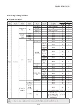
Page 15: ... waycassette SwingON SwingOFF360cassette Spot Mid Wide Motiondetect sensor SetMotion detectsensor ON OFF OFF Motion detectiontype IndirectWind DirectWind IndirectWind Option Usermode Language Differsdependingonthe language Firstvaluefor thelanguage pack DaylightSaving Time DaylightSaving Time ON OFF OFF ON Unit Day Week Week Week StartMonth JanuarytoDecember Mar Mar StartWeek 1stto4th Final finalw...

Page 16: ...ock ON OFF OFF Automode Lock ON OFF OFF Coolmode Lock ON OFF OFF Drymode Lock ON OFF OFF Heatmode Lock ON OFF OFF Fanmode Lock ON OFF OFF Temperature Lock ON OFF OFF FanspeedLock ON OFF OFF AdditionalMode Lock Wind Free Lock ON OFF OFF LongWind Lock ON OFF OFF QuietLock ON OFF OFF SleepLock ON OFF OFF ScheduleLock ON OFF OFF Wiredremote controller LED ON OFF OFF ButtonMute ON OFF OFF Wireless remo...

Page 17: ...ettemprangeforauto operationoftheindoor unit Indoor unitstatus value Primary 0 5 to2 or1 to4 Indoor unitstatus value Secondary 0 5 to2 or1 to4 Indoor unitstatus value Temperature limits LowerLimit Celsius 8to30 Fahrenheit 47to86 8 UpperLimit Celsius 8to30 Fahrenheit 47to86 30 Easytuning 2to 2 0 lightingIndoor ON OFF Indoor unitstatus value Clean ON OFF Indoor unitstatus value Delaytime UseofERV de...

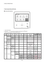
Page 18: ...rvice mode appears 3 See the list of additional functions for the Wired Remote Controller on the next page and then select the desired menu Once you have entered the setting screen the current setting appears Refer to the chart for data setting Using the buttons change the settings and press the button to move to the next setting Press the button to save the new setting Press the button to move to...

Page 19: ... Heat Wirelessremote controller ON OFF ON MAIN SUBwired remote Master Slave Master Temperatureunit Temperatureunit Celsius C Fahrenheit Celsius C Fahrenheit Settemp Unit Celsius 1 0 5 0 1 Fahrenheit 1 1 1 Temperaturesensor selection Indoor Wiredremotecontroller Indoor Wiredremote controller Averagetemperature ON OFF OFF SetTemperatureType ON OFF ON Connection Information NumberofConnection Indoor ...

Page 20: ...Ccode Programversion Modifieddate Graphicimage Graphicimagecode Programversion Modifieddate ResetAll Servicemodes EraseAllServicemode data Initializearemote controller PowerMaster Reset ODUK3reset Outdoor capacity ON OFF Indoor Bladelock4 Blade1 Unlock Lock Unlock Blade2 Unlock Lock Unlock Blade3 Unlock Lock Unlock Blade4 Unlock Lock Unlock Room Temperature Calibration Referencetemperature 9to40 C...

Page 21: ...tepSetting VentilationRPM 0to31STEP ExhaustRPM 0to31STEP ERVStatusInformation ERVEnergy saving operation ON OFFAlternation operation ON OFFalternationoperation Outdooraircoolingoperation fordifferenttemp setting ON OFF alternation operation Minimumtemp of outdooraircooling 5to15 C 15 C ERVPlus Coldairprevention ON OFF Humidificationwhen Heatingthermooff ON OFF FanoperationinDefrost ON OFF Humidifi...

Page 22: ... VentilationRPM 10to27STEP ExhaustRPM 10to27STEP 1 Setting is available when there is only 1 indoor unit connection and while the indoor unit operation is not operating 2 Power Master Reset is a setting needed to supply optimized power to wired remote controller when multiple indoor units are connected to wired remote controller in a group 3 The total option codes are 24 digits You can set six dig...

Page 23: ...uct option Installation option1 Installation option 2 Address is displayed in hexadecimal Please refer to the following table NOTE Hexadecimal Decimal Hexadecimal Decimal Hexadecimal Decimal Hexadecimal Decimal Hexadecimal Decimal 00 0 10 16 20 32 30 48 40 64 01 1 11 17 21 33 31 49 41 65 02 2 12 18 22 34 32 50 42 66 03 3 13 19 23 35 33 51 43 67 04 4 14 20 24 36 34 52 44 68 05 5 15 21 25 37 35 53 4...

Page 24: ...ption and then press the button 4 Press the and buttons to select Cool Heat selection and then press the button The menu with the shape can be selected using the button 5 Press the and buttons to select Cool Only and then press the button to finish the setting 6 Press the button to move to the Home screen Feature expansion specification The example of Wired Remote Controller option setting method ...

Page 25: ...ate it to lift the front cover for removal from the rear cover 2 Arrange the power cable and the communication cable so that they fit in the housing along the edges of the rear cover When the cable is not concealed When the cable is concealed 8 cm 3 15 inch 8 cm 3 15 inch Area A When connecting the power and communication cables to the bottom of the Wired Remote Controller first cut off the area A...

Page 26: ... You must fit the screws into the screw holes 10 mm 0 4 inch or more 10 mm 0 4 inch or more 50 mm 2 inch or more 10 mm 0 4 inch or more Screw hole Rear cover 4 Connect the communication cables F3 F4 to the terminals of the back of the front cover and then fix the wires so that they do not get stuck during connection Do not tighten the screws on the PCB terminal with excessive force F3 F3 F4 F4 V1 ...

Page 27: ... that is connectable to Wired Remote Controller PCB If you install the Wired Remote Controller by reclaiming install it according to U terminal cable specification If you install the Wired Remote Controller by using two pieces of PVC wire remove the 30 cm 12 inch of the sheath of the cable and install it only with the two pieces of wires Recommended specification AWG20 SOL The following are the sp...

Page 28: ...ttons at the same time for more than 5 seconds The system will reset and tracking will start again 3 During tracking the total number of currently searched indoor units and ventilator ERV will be displayed 4 It may take about 5 minutes at initial installation or when you re set the Master setting The operation displays on the remote controller may differ depending on the selected language If you w...

Page 29: ...k 1 1 Use the flat blade screwdriver to slide the bottom two grooves into the product Push CASE TOP up and remove CASE BOTTOM When assembling assemble the upper side first as shown and lower Assemble with hook WARING 2 2 Unscrew 4 SCREW assemblies on CASE TOP to separate PBA ...

Page 30: ...Disassemblyand assembly 3 2 NO Photo How to work 3 3 Remove the HOLDER DISPLAY hook assembled with the PBA 4 4 Remove the LCD connector to separate the PBA and the ASSY Display ...

Page 31: ...n No communication between Master Main and Slave Sub Wired Remote Controllers communication stop for 3 minutes after detection When tracking between the Wired Remote Controller and indoor units ventilators ERV is not complete for more than 5 minutes Including communication error between indoor units and outdoor units Over 16 indoor units and ventilators ERV installed Reset is required after checki...

Page 32: ...4 terminal 9 12V F3F4 terminal 9 12V C108 Is the voltage C108 Is the voltage between 18 24V between 18 24V Does it work normally Does it work normally after replacing after replacing ASSY DISPLAY LCD Replacement ASSY DISPLAY LCD Replacement DB93 16995A DB93 16995A C115 Is the voltage between C115 Is the voltage between both ends 5V both ends 5V Is the LCD connector Is the LCD connector connected p...

Page 33: ...icator signal Processor Two Wired Communication Part Super capacitor for current time keeping 5V Power Supply part Temperature Sensor DB95 04690A MICOM EEPROM IMAGE IC TOUCH IC RTC IC Transformer Communicator part Backlight Power Super Capacitor microSD SLOT 5V Power BUZZER 3 3V Power Temperature Sensor 7 3 11 13 2 1 9 5 8 4 14 10 12 6 ...

Page 34: ...Wiring diagram 6 1 6 Wiring diagram microSD SLOT Download Connecter Temperature SensorConnecter F3F4 TerminalBlock ...

Page 35: ...y when the file version in the microSD Card differs from the one of the Wired Remote Controller When the screen is frozen for more than 3 minutes after completing the microSD card update by 100 product inspection is required Delete the files except for the ones for download Only IMAGE BIN and MICOM BIN are required When the microSD Card is removed during download 1 When you remove the microSD Card...

Page 36: ... Electronics Co Ltd Any unauthorized use of Manual can be punished under applicable International and or domestic law GSPN GLOBALSERVICE PARTNER NETWORK Area Web Site Europe CIS Mideast Africa gspn1 samsungcsportal com Asia gspn2 samsungcsportal com North Latin America gspn3 samsungcsportal com China china samsungportal com ...

Reviews: