background image

5.

PCB Diagram

5. PCB Diagram

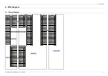
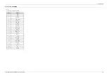
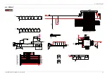
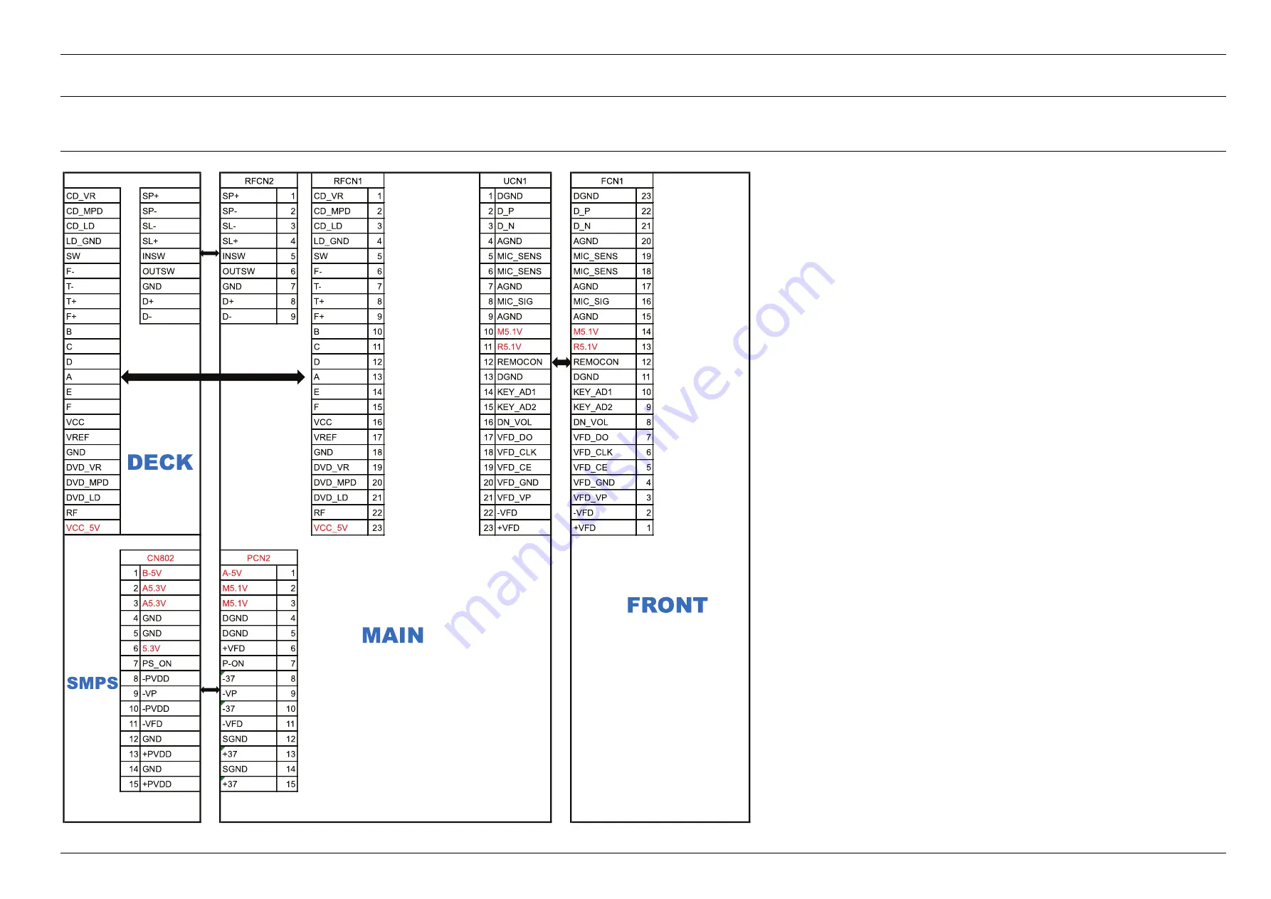
5.1. Wiring Diagram

CD_VR

SP+

SP+

1

CD_VR

1

1 DGND

DGND

23

CD_MPD

SP-

SP-

2

CD_MPD

2

2 D_P

D_P

22

CD_LD

SL-

SL-

3

CD_LD

3

3 D_N

D_N

21

LD_GND

SL+

SL+

4

LD_GND

4

4 AGND

AGND

20

S W

INSW

INSW

5

S W

5

5 MIC_S ENS

MIC_S ENS

19

F-

OUTS W

OUTS W

6

F-

6

6 MIC_S ENS

MIC_S ENS

18

T-

GND

GND

7

T-

7

7 AGND

AGND

17

T+

D+

D+

8

T+

8

8 MIC_S IG

MIC_S IG

16

F+

D-

D-

9

F+

9

9 AGND

AGND

15

B

B

10

10

M

5.1V

M5.1V

1

4

C

C

11

11 R

5.1V

R5.1V

1

3

D

D

12

12 REMOCON

REMOCON

12

A

A

13

13 DGND

DGND

11

E

E

14

14 KEY_AD1

KEY_AD1

10

F

F

15

15 KEY_AD2

KEY_AD2

9

VCC

VCC

16

16 DN_VOL

DN_VOL

8

VREF

VREF

17

17 VFD_DO

VFD_DO

7

GND

GND

18

18 VFD_CLK

VFD_CLK

6

DVD_VR

DVD_VR

19

19 VFD_CE

VFD_CE

5

DVD_MPD

DVD_MPD

20

20 VFD_GND

VFD_GND

4

DVD_LD

DVD_LD

21

21 VFD_VP

VFD_VP

3

RF

RF

22

22 -VFD

-VFD

2

VCC_5

V

VCC_5 V

2

3

23 +VFD

+VFD

1

1 B-5V

A-5V

1

2 A5.3V

M5.1V

2

3 A5.3V

M5.1V

3

4 GND

DGND

4

5 GND

DGND

5

6 5.3V

+VF

D

6

7 PS_O N

P-O N

7

8 -PVDD

-37

8

9 -VP

-VP

9

10 -PVDD

-37

10

11 -VFD

-VFD

11

12 GND

S GND

12

13 +PVDD

+37

13

14 GND

S GND

14

15 +PVDD

+37

15

RFC

N2

RFC N1

UCN1

FCN1

MAI

N

SMPS

DECK

F R O N T

CN80

2

PCN2

Copyright© 1995-2013 SAMSUNG. All rights reserved.

5-1

Summary of Contents for MX-F730

Page 1: ...730 ZD SERVICEMANUAL MINI Compact System MX F730 Contents 1 Precaution 2 Product Specification 3 Disassembly and Reassembly 4 Troubleshooting 5 PCB Diagram 6 Schematic Diagram Refer to the service manual in the GSPN see the rear cover for more information ...

Page 2: ...4 4 2 Measures to be taken when the Protection Circuit operates 4 5 4 2 1 Operation of Power Block Protection Circuit 4 5 4 2 2 Check AMP in Power Protection 4 6 4 3 MICOM MPEG Initialization Update 4 7 4 4 Buyer Region Code Setting Method 4 8 4 4 1 The inserting method of Region Code after replacing the Main PBA 4 8 5 PCB Diagram 5 1 5 1 Wiring Diagram 5 1 5 2 FRONT PCB Top 5 2 5 2 1 Pin Connecti...

Page 3: ...Contents 6 3 MAIN 1 6 3 6 4 MAIN 2 6 4 6 5 MAIN 3 6 5 6 5 1 Test Point Wave Form 6 6 6 6 MAIN 4 6 7 6 7 MAIN 5 6 8 6 8 SMPS 1 6 9 6 9 SMPS 2 6 10 Copyright 1995 2013 SAMSUNG All rights reserved ii ...

Page 4: ...ch alterations might create a safety hazard Also any design changes or additions will void the manufacturer s warranty 4 Leakage Current Hot Check Figure 1 1 AC Leakage Test WARNING Do not use an isolation transformer during this test Use a leakage current tester or a metering system that complies With the unit completely reassembled plug the AC cord directly into a AC outlet With the unit s power...

Page 5: ...rrect any potential hazards 7 Observe the original lead dress especially near the following areas Antenna wiring sharp edges and especially the AC and high voltage power supplies Always inspect for pinched out of place or frayed wiring Do not change the spacing between components and the printed circuit board Check the AC power cord for damage Make sure that no wires or components touch thermally ...

Page 6: ...nsulation between the blades of the AC plug and accessible conductive parts examples metal panels input terminals and earphone jacks 6 Insulation Checking Procedure Disconnect the power cord from the AC source Connect an insulation resistance meter 500 V to the blades of the AC plug The insulation resistance between each blade of the AC plug and accessible conductive parts see above should be grea...

Page 7: ... not use freon propelled chemicals These can generate electrical charges that damage ESDs 4 Use only a grounded tip soldering iron when soldering or unsoldering ESDs 5 Use only an anti static solder removal device Many solder removal devices are not rated as anti static these can accumulate sufficient electrical charge to damage ESDs 6 Do not remove a replacement ESD from its protective package un...

Page 8: ... 550 W Total RMS 6000 W PMPO IR Amp Specialized Function CD Ripping Able to ripping while listening New Bass Sound System Called GIGA Sound Connectivity USB MIC Disc Type 1 Tray Compatible DVD Divx Only MX F730D MP3 CD CD R RW WMA 2 1 Copyright 1995 2013 SAMSUNG All rights reserved ...

Page 9: ...ed 4 8 5 6 m sec CD Disc CD 12 cm Compact Disc Maximum Play Time 74 min Total Output Power 550 Watts MAX Front speaker output 275 W CH 4 Ω 100 Hz Frequency range 20 Hz 20 KHz S N Ratio 80 dB Channel separation 65 dB Amplifier Input sensitivity AUX 800 mV NOTE Samsung Electronics Co Ltd reserves the right to change the specifications without notice Weight and dimensions are approximate Design and s...

Page 10: ...FRONT DISPLAY VFD VFD VFD DIMMER O O O Bluetooth X X X CD DVD CD CD DVD CD DVD MP3 O O O USB HOST O O O CD RIPPING O O O TAPE X X X AUDIO IN O O O HEADPHONE X X O FM RDS FM AM FM AM RDS RUSSIA ONLY FM AM REMOTE KEY 45 KEY 45 KEY 45 KEY DUAL VOLTAGE X X O SPK IMPENDANCE 3 5 OHM 3 5 OHM 4 OHM TIP O Feature Included X Not Included 2 3 Copyright 1995 2013 SAMSUNG All rights reserved ...

Page 11: ...ied Accessories Accessories Item Item code Batteries AAA 4301 000121 TUNER AUX REPEAT GIGA REPEAT A B AUTO CHANGE Remote Control AH59 02531A User s Manual AH68 02604L FM AM Antenna Optional AH42 00036A Copyright 1995 2013 SAMSUNG All rights reserved 2 4 ...

Page 12: ...ead and understand the safety instructions before performing any work as the IC chips on the PCB are vulnerable to static electricity In order to assemble reverse the order of disassembly Description Description Photo 1 Power on and Open the Deck Separate CD Door 2 Unfasten 4 screws on the 2 side Cover BH 3 10 BLACK CAUTION Be careful not to make any scratches as you remove them 3 1 Copyright 1995...

Page 13: ...3 Disassembly and Reassembly Description Description Photo 3 Unfasten 2 screws on the back Cover BH 3 10 BLACK Copyright 1995 2013 SAMSUNG All rights reserved 3 2 ...

Page 14: ...3 Disassembly and Reassembly Description Description Photo 4 Separate the Front panel 3 3 Copyright 1995 2013 SAMSUNG All rights reserved ...

Page 15: ... Description Description Photo 5 Unfasten 5 Screws in SMPS and detach AC CORD 15P shield wire BH 3 10 WHITE 6 Unfasten 2 screws up the DECK Separate DECK from MECHA BH 3 10 BLACK Copyright 1995 2013 SAMSUNG All rights reserved 3 4 ...

Page 16: ...mbly Description Description Photo 7 Unfasten 2 screws and detach DECK wire BH 3 10 WHITE 8 Unfasten 10 screws and then separate the front PCB from Front Panel BH 3 10 WHITE 3 5 Copyright 1995 2013 SAMSUNG All rights reserved ...

Page 17: ...3 Disassembly and Reassembly 3 2 DECK Disassembly and Reassembly Description Description Photo 1 Separate Tray Disc from DECK Copyright 1995 2013 SAMSUNG All rights reserved 3 6 ...

Page 18: ...3 Disassembly and Reassembly Description Description Photo OPEN CLOSE OPEN CLOSE HOOK HOOK HOOK HOOK 3 7 Copyright 1995 2013 SAMSUNG All rights reserved ...

Page 19: ...3 Disassembly and Reassembly Description Description Photo 2 Lift up Holder Cable separate Traverse DECK HOOK HOOK HOOK HOOK Copyright 1995 2013 SAMSUNG All rights reserved 3 8 ...

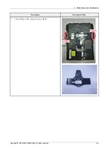
Page 20: ...d Reassembly Description Description Photo 3 Disassemble complete Holder Cable Holder Cable Traverse Deck Traverse Deck Tray disc Tray disc Holder Chuck Holder Chuck 3 9 Copyright 1995 2013 SAMSUNG All rights reserved ...

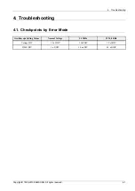
Page 21: ...ooting 4 1 Checkpoints by Error Mode Oscilloscope Setting Values Normal Voltage 24 MHz 32 768 KHz Voltage DIV 1 Vol DIV 1 Vol DIV 1 Vol DIV TIME DIV 1 uS DIV 10 ns DIV 0 1 uS DIV Copyright 1995 2013 SAMSUNG All rights reserved 4 1 ...

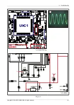
Page 22: ...Check VFD Voltage on MAIN PCB PCN2 6 11 1 Check CLOCK circuit in MAIN PCB X TAL1 part ok Check MAIN PCB CN2 2 3 5 1V Check or replace SMPS Check signal and signal pattern Check or replace SMPS No Check or replace SMPS Yes Yes Yes Yes Yes Check MAIN PCB VFQ1 VFQ2 Refer to wave pattern image of Fig 4 1 4 2 Copyright 1995 2013 SAMSUNG All rights reserved ...

Page 23: ...16 150OHM P13 P14 C2021 10V 1UF UAR1A TPTX DGND R2021 2 2KOHM Q3 Q2 Q1 Q0 RESET RESET VDD GND M5 1V_PW 100NF TUGND 2 2UF 10NF 1KOHM 22PF 32 768H Z MC 146 32 768KHZ 20PPM 100NF S 6415A42 M 3T1U 100NF DGND 22PF 50V 22PF 22KOHM 50V 22PF DGND 10UF 10V 0 01OHM 1KOHM 220PF 220PF 220PF 1MOHM 150OHM 10V 1UF DGND 2 2KOHM UC6 C2013 R2001 C2015 X_TAL1 C2017 IC2001 C2019 C2026 C2018 R3002 C2020 C2022 BD2001 R...

Page 24: ...b ON AUDIO no output Check ALQ31 ALQ41 ARQ31 ARQ41 IRF6645 output signal on MAIN PCB Check L2001 L2002 Choose the correct function or turn on the Volume Replace AIC2 on MAIN PCB IRF6645 Replace MIC1 on MAIN PCB ES8396 Change the function Replace L2001 L2002 Check L2001 L2002 pattern Yes Yes Yes Yes Yes 4 4 Copyright 1995 2013 SAMSUNG All rights reserved ...

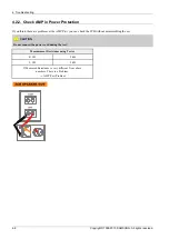
Page 25: ...ver current at the AMP IC Speaker Wire Short 2 If temperature of the AMP IC is over 150 3 There is no power supply for amp Protection Circuit operates when power problem occurs in the SMPS Protection Location Pin No Open Short Remark 5 3 V 2 3 X X PVDD 34V 13 15 X X PVDD 10 X X MX F730 F730D SMPS PCB CNM802 P ON 5 V 7 X X Copyright 1995 2013 SAMSUNG All rights reserved 4 5 ...

Page 26: ...PCB without disassembling the set CAUTION Do not connect the power cord during the test Measurement Resistance using Tester R CH 2 kΩ L CH 2 kΩ If Measured Resistance is very different from above numbers There is a Problem AMP Part Problem 2 CH S P EAKER OUT RIGHT LEFT 4 6 Copyright 1995 2013 SAMSUNG All rights reserved ...

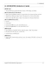
Page 27: ...ate will be displayed Set will be power off when finish Micom MPEG Version Check 1 Power On 2 CD open status 3 Push the number NEXT for 5 seconds check the MICOM version 4 Push the number PREVIOUS for 5 seconds check the MPEG version MPEG Update 1 Insert USB Memory or Update DISC which have Update file and play Update will be displayed 2 When finish the Set will be power off on automatically 3 And...

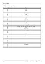
Page 28: ...code The region code is inserted by the remote control 1 During AUX status MX F730 F730CB Push the ENTER button 10 Second MX F730D Push the D button blue key 10 Second MX F730 MX F730D 2 When displayed TEST import 46 to set the buyer TEST 3 When displayed import the buyer code The buyer setting code can find in the table named MX F7 _Opption_Table 4 It will show the buyer that you set up Then the ...

Page 29: ... Indonesia Asia Hongkong 66 67 KOR 68 Latin American 69 Mexico 70 Philippines 71 72 Russia semi_mic 73 M E Asia Israel Saudi Argentina Uruguay Turkey MIC 74 Taiwan 75 USA Canada 76 New Zealand Australia 77 78 79 Iran HACO 80 India 81 82 83 84 85 86 87 KOR for test 88 89 Copyright 1995 2013 SAMSUNG All rights reserved 4 9 ...

Page 30: ... Asia Hongkong 96 97 KOR 98 Latin American 99 Mexico 100 Philippines 101 102 Russia semi_mic 103 M E Asia Israel Saudi Argentina Uruguay Turkey MIC 104 Taiwan 105 USA Canada 106 New Zealand Australia 107 108 109 Iran HACO 110 India 111 112 113 114 115 116 117 KOR for test 118 119 4 10 Copyright 1995 2013 SAMSUNG All rights reserved ...

Page 31: ... 13 13 DGND DGND 11 E E 14 14 KEY_AD1 KEY_AD1 10 F F 15 15 KEY_AD2 KEY_AD2 9 VCC VCC 16 16 DN_VOL DN_VOL 8 VREF VREF 17 17 VFD_DO VFD_DO 7 GND GND 18 18 VFD_CLK VFD_CLK 6 DVD_VR DVD_VR 19 19 VFD_CE VFD_CE 5 DVD_MPD DVD_MPD 20 20 VFD_GND VFD_GND 4 DVD_LD DVD_LD 21 21 VFD_VP VFD_VP 3 RF RF 22 22 VFD VFD 2 VCC_5 V VCC_5 V 23 23 VFD VFD 1 1 B 5V A 5V 1 2 A5 3V M5 1V 2 3 A5 3V M5 1V 3 4 GND DGND 4 5 GN...

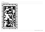
Page 32: ...5 PCB Diagram 5 2 FRONT PCB Top FCN 1 1 5 2 Copyright 1995 2013 SAMSUNG All rights reserved ...

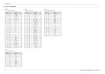
Page 33: ...Pin No Signal 1 VFD 2 VFD 3 VFD_VP 4 VFD_GND 5 VFD_CE 6 VFD_CLK 7 VFD_DO 8 DN_VOL 9 KEY_AD2 10 KEY_AD1 11 DGND 12 REMOCON 13 R5 1V 14 M5 1V 15 AGND 16 MIC_SIG 17 AGND 18 MIC_SENS 19 MIC_SENS 20 AGND 21 D_N 22 D_P 23 DGND Copyright 1995 2013 SAMSUNG All rights reserved 5 3 ...

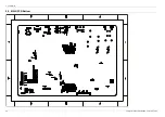
Page 34: ...5 PCB Diagram 5 3 FRONT PCB Bottom 5 4 Copyright 1995 2013 SAMSUNG All rights reserved ...

Page 35: ...B Diagram 5 4 MAIN PCB Top RFCN 2 JIG CN UCN1 CN1 RF CN 1 RF IC2 RFIC1 TIC1 MIC 1 UIC1 UIC3 MP IC2 AIC2 AIC1 MIC2 MIC3 MIC4 P CN2 BT CN 1 UCN3 3 TP1 4 1 2 Copyright 1995 2013 SAMSUNG All rights reserved 5 5 ...

Page 36: ...SP 3 SL 4 SL 5 INSW 6 OUTSW 7 GND 8 D 9 D 3 UCN1 FRONT Panel Control Pin No Signal 1 DGND 2 D_P 3 D_N 4 AGND 5 MIC_SENS 6 MIC_SENS 7 AGND 8 MIC_SIG 9 AGND 10 M5 1V 11 R5 1V 12 REMOCON 13 DGND 14 KEY_AD1 15 KEY_AD2 16 DN_VOL 17 VFD_DO 18 VFD_CLK 19 VFD_CE 20 VFD_GND 21 VFD_VP 22 VFD 23 VFD 4 PCN2 VFD CD AMP Voltage Supply Pin No Signal 1 A 5V 2 M5 1V 3 M5 1V 4 DGND 5 DGND 6 VFD 7 P ON 8 37 9 VP 10 ...

Page 37: ...5 PCB Diagram 5 4 2 Test Point Wave Form TP1 Copyright 1995 2013 SAMSUNG All rights reserved 5 7 ...

Page 38: ...5 PCB Diagram 5 5 MAIN PCB Bottom 5 8 Copyright 1995 2013 SAMSUNG All rights reserved ...

Page 39: ...5 PCB Diagram 5 6 SMPS PCB Top Comply with the threshold of substances which are specified in 0QA_209 CN8 0 2 1 Copyright 1995 2013 SAMSUNG All rights reserved 5 9 ...

Page 40: ...Pin Connection 1 CN802 VFD CD AMP Voltage Supply Pin No Signal 1 B 5V 2 A5 3V 3 A5 3V 4 GND 5 GND 6 5 3V 7 PS_ON 8 PVDD 9 VP 10 PVDD 11 VFD 12 GND 13 PVDD 14 GND 15 PVDD 5 10 Copyright 1995 2013 SAMSUNG All rights reserved ...

Page 41: ...5 PCB Diagram 5 7 SMPS PCB Bottom Comply with the threshold of substances which are specified in 0QA_209 Copyright 1995 2013 SAMSUNG All rights reserved 5 11 ...

Page 42: ...Video 8K EEPROM 2MFlash DVD Tuner Control Pre AMP 7 30 FL FR USB CrystalPro IR Amp 730 Au dio De c ode r DAC lThe Main Micom IC is R5F100PGAFB MPEG IC is ES8396SCD AMP IC is IRF6645 The Main Micom control each IC in this PCB Video signal is come from DVD Mecha and go to the MPEG IC Then MPEG IC decode this signal to real video signal Audio signal is come from DVD Mecha TUNER AUX MIC Then MPEG IC e...

Page 43: ...20 P19 7G P18 P17 6G P16 P15 P14 5G P13 P12 P11 4G P10 P9 P8 3G P7 P6 2G P5 P4 P3 P2 P1 F F VFD VFD VP DGND VFD_CLK VFD_DO VFD_CE JOG KEY_2 KEY_1 DGND JOG REMOCON R5 1V 5 1V MIC_SEN UGND D_P D_N U5 4V MIG_SIG MGND MGND STOP REW EQ MP3 CD POWER OPEN TURNER AUX DELETE USB USB RE C OPEN GLOS E GIGA PARTY DEMO R5 1V 5 1V 5 1V FCZ100E 23SS K MIC_AGND1 UNDEFINED UNDEFINED 3857ST MGND 16V 10NF 1 8W 10KOH...

Page 44: ...AR8 100KOHM IN2 VEE OUT2 VCC IN2 IN1 IN1 OUT1 E B C E B C E B C E B C E B C E B C 37V VP VFD 37V SGND 37V SGND M5 1V A 5V DGND DGND VFD P ON M5 1V 37V FROM SMPS 37V_PW 25V_PW A 5V_PW M5 1V_PW 25V_PW 37V_PW A 5V_PW A 5V_PW A 5V_PW 50V 1 2KOHM 1 5NF 50V 33KOHM TWG P15P A1 50V 100NF 50V 100NF S_GND 1 5OHM 1 5OHM 50V 100NF 2 2MF 50V 50V 2 2MF 50V 100NF 50V 100NF 50V 100NF 50V 100NF 100NF 50V 100NF 50V...

Page 45: ...C IN GND VAA E B C HO CSH OCSET VREF COM DT VSS CSD LO COMP VS VB VCC IN GND VAA 5 6K 4 7K 40NS 8 2K 3 3K 65NS 5 6K 4 7K 40NS 8 2K 3 3K 65NS 2203 007598 2203 007598 25V_PW 25V_PW 37V_PW A 5V_PW A 5V_PW A 5V_PW 37V_PW 37V_PW A 5V_PW 10UF 100NF 10UF 4 7OHM 100 MBRS1100T3 1N4148 WS 47KOHM DGND 1 8KOHM 10OHM 470NF 1SR154 400TE25 43KOHM S_GND 100NF SRC1 203S DGND 1NF 50V 220OHM 2SA1037AK 100PF 10V 10UF...

Page 46: ...PO1 GPO2 INT GPO3 DCLK Q3 Q2 Q1 Q0 RESET RESET VDD GND SDA VSS WC VCC SCL E2 NC NC E B C VFD_CLK VFD_DO KEY_AD2 MAIN FRONT PC B 4730 USE TIC1 1204 003 345 1204 003 347 1204 002 700 OPTION RDS AM FM 4730 SPEC 4705 4702 OMIT OMIT TUR9 OMIT 0 OHM 0 OHM 0 OHM TUR18 GND MIC_SIG MIC_SENS USB5 2V AGND D_N D_P 5 1V 5 1V DGND REMOTE AGND KEY_AD1 JOG JOG VFD VFD_CE DGND 28V VFD RES T 5V RX TX GND M5 1V_PW U...

Page 47: ...6 Schematic Diagram 6 5 1 Test Point Wave Form TP1 Copyright 1995 2013 SAMSUNG All rights reserved 6 6 ...

Page 48: ...UDQM CLK CKE NC A11 A9 A8 A7 A6 A5 A4 VSS VDD A3 A2 A1 A0 A10 AP A12 SDA VSS WC VCC SCL E2 NC NC BT OPTION PLL2 1 1 1 1 0 1 1 0 0 0 0 0 0 1 1 1 0 0 DVD CD PLL1 1 1 0 1 0 0 PLL0 MIC2 4 5 64MBIT 1105 001585 4 75 MULTI BYPASS 128MBIT 1105 001573 5 5 5 75 5 0 5 25 6 0 162 148 5 0 1 135 N A 121 5 141 75 128 25 155 25 FREQ 1 S_L 0 1 OTP 0 PL3 NORMAL MODE TEST MODE S_P_OPTION DCLK INPUT CLK SOURCE CRYSTA...

Page 49: ...FB AGND VIN PGND B C E S D G E B C E B C E B C IN2 GND OUT2 VCC IN2 IN1 IN1 OUT1 DVD_LD DVD_MPD CD AUX OPTION CD OPTION OUTSW D D INSW SL SL SP GND SP SW CD_VR CD_MPD CD_LD T LD_GND F EMC IMPROVE T D C B F VREF VCC E A F GND VCC_5V RF DVD_VR DVD OPTION DVD OPTION DVD VIDEO OPTION 10V M5 1V_PW MP3 3V_PW DM5V_PW MP3 3V_PW M5 1V_PW USB5V_PW M5 1V_PW DM5V_PW RF5V_PW RF5V_PW RF5V_PW MP3 3V_PW MP3 3V_PW...

Page 50: ... 1608 CM810 50V 100nF 1608 DM902 SFF1606G DM902 SFF1606G ZDM802 MMS Z5239B 9 1V ZDM802 MMS Z5239B 9 1V LM804 BAS 3550TO LM804 BAS 3550TO QM806 KTN2907AS SOT 23 QM806 KTN2907AS SOT 23 DM808 US1M DM808 US1M LM902 2 9uH 1 2 LM902 2 9uH 1 2 CM811 50V 101 1608 CM811 50V 101 1608 CM813 50V 10nF 2012 CM813 50V 10nF 2012 RM906 24K 2012 RM906 24K 2012 ZDM905 MMS Z5248 18V ZDM905 MMS Z5248 18V CA801 250V 47...

Page 51: ...3216 RS953 30K 3216 RS 914 1K 2012 RS 914 1K 2012 QS 951 S KTC322 8 QS 951 S KTC322 8 RS 956 100K 3216 RS 956 100K 3216 CS931 35V 470uF CS931 35V 470uF RS933 1K 1608 RS933 1K 1608 RS 909 NC RS 909 NC CS 905 50V 33pF 1608 CS 905 50V 33pF 1608 RS 803 22 1608 RS 803 22 1608 QS 932 S MMBT2907A SOT 23 QS 932 S MMBT2907A SOT 23 DS901 MBRF20200CT DS901 MBRF20200CT RS812 NC RS812 NC P CS 801S B ETV817S P ...

Page 52: ...na Japan https gspn2 samsungcsportal com N America S America https gspn3 samsungcsportal com This Service Manual is a property of Samsung Electronics Co Ltd Any unauthorized use of Manual can be punished under applicable International and or domestic law 2013 Samsung Electronics Co Ltd All rights reserved Printed in Korea ...

Reviews: