4. Troubleshooting
4.1.1. No Power
No
No
No
No
No
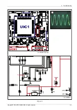
Che ck MAIN P CB
UCN1 10# : VF5.1V.
Che ck MAIN P CB
UIC1 P IN53:5.1V.
No P owe r
Che ck pa tte rn or re pla ce
MICOM IC.
Check VFD
Voltage on MAIN PCB
PCN2 6, 11# .
(1)
Che ck CLOCK circuit in
MAIN P CB X-TAL1
pa rt ok?
Che ck MAIN P CB
CN2 2~3# (5.1V).
Che ck or re pla ce S MP S .
Che ck s igna l
a nd s igna l pa tte rn.
Che ck or re pla ce S MP S .
No
Che ck or re pla ce S MP S .
Ye s
Ye s
Ye s
Ye s
Ye s
C
he ck MAIN P CB
VFQ1 ;VFQ2 .
* R
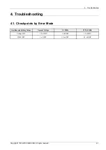
e fe r to wa ve pa tte rn
ima ge of Fig. 4-1.
4-2
Copyright© 1995-2013 SAMSUNG. All rights reserved.
Summary of Contents for MX-F730
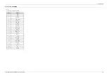
Page 32: ...5 PCB Diagram 5 2 FRONT PCB Top FCN 1 1 5 2 Copyright 1995 2013 SAMSUNG All rights reserved ...
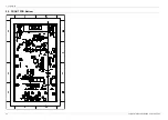
Page 34: ...5 PCB Diagram 5 3 FRONT PCB Bottom 5 4 Copyright 1995 2013 SAMSUNG All rights reserved ...
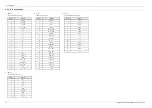
Page 38: ...5 PCB Diagram 5 5 MAIN PCB Bottom 5 8 Copyright 1995 2013 SAMSUNG All rights reserved ...


