5.
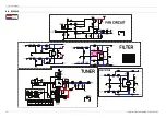
PCB Diagram
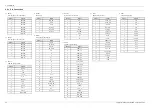
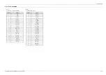
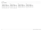
5.5.1. Pin Connection
1) FCN5
AUX/MIC/USB Control
Pin No.
Signal
1
USB1_5V
2
USB1_5V
3
USB1_DN
4
USB1_DN
5
USB1_DP
6
USB1_DP
7
USB1_GND
8
USB1_GND
9
USB2_5V
10
USB2_5V
11
USB2_DN
12
USB2_DN
13
USB2_DP
14
USB2_DP
15
USB2_GND
16
USB2_GND
17
AUX1_L
18
AGND
19
AUX1_R
20
AGND
21
MIC_SIGN
22
MIC_SEN
23
AUX1_SEN
2) FCN4
VOLUME/KEY Control
Pin No.
Signal
1
DGND
2
REMOCON
3
KEY_AD2
4
KEY_AD3
5
ST5.1V
6
LED_5.1V
7
VOL_UP
8
VOL_DN
9
VOL_LED6
10
VOL_LED5
11
VOL_LED4
12
VOL_LED3
13
VOL_LED2
14
VOL_LED1
15
FLEDBR
16
FLEDB
17
FLEDBL
18
FLED9
19
DGND
20
DGND
21
DGND
Copyright© 1995-2013 SAMSUNG. All rights reserved.
5-8
Summary of Contents for MX-F870
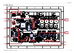
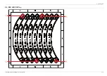
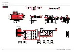
Page 40: ...5 PCB Diagram 5 3 MAIN PCB Bottom 5 5 Copyright 1995 2013 SAMSUNG All rights reserved...
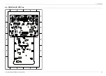
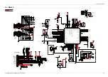
Page 41: ...5 PCB Diagram 5 4 FRONT JACK PCB Top Copyright 1995 2013 SAMSUNG All rights reserved 5 6...
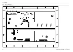
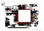
Page 49: ...5 PCB Diagram 5 9 SPK LED PCB Bottom Copyright 1995 2013 SAMSUNG All rights reserved 5 14...
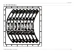
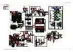
Page 52: ...5 PCB Diagram 5 11 SMPS PCB Bottom 5 17 Copyright 1995 2013 SAMSUNG All rights reserved...

