background image

6

English

Tools and Parts 

Removing the packaging

CAUTION

Remove the carton carefully. Wear gloves to protect against sharp edges.

  WARNING


Remove the protective film covering the product before putting into 

operation. 


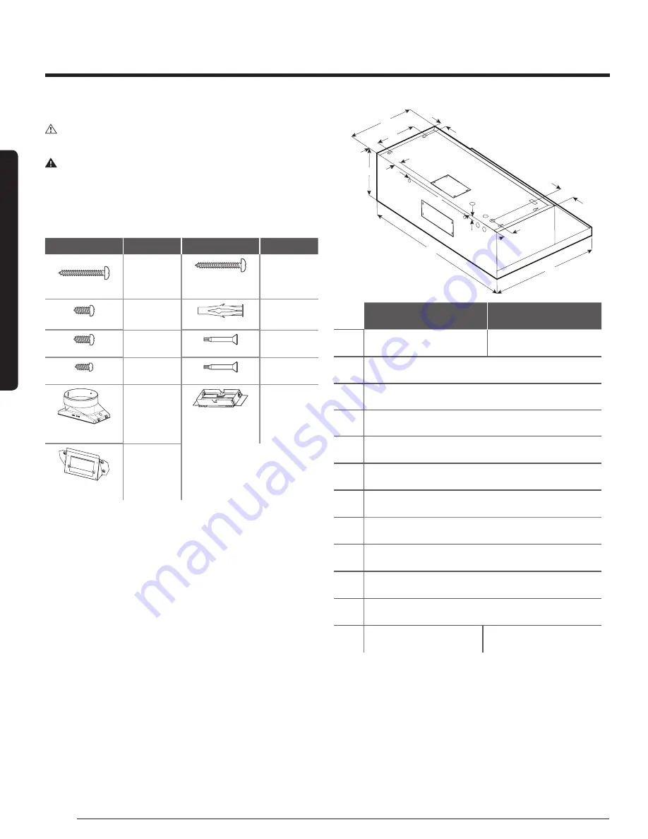
Parts supplied


Hood assembly with blower and LED lamps already installed.


Hardware bag with: 

Part

Qty

Part

Qty

5x45 mm

4

5.4x75 mm screws 
(for 10x60 mm wall 

anchors)

4

4.5x13 mm

4


10 x 60 mm

4

3.5x9.5 mm

2


Torx 10 adapter

1

4.2x8 mm

7


Torx 20 adapter

1

6” (15.2 cm) round 

transition

1

Rectangular transition 

3

1

4

” x 10” (8.3 x 25.4 

cm) with back draft 

dampers

1


Rear blower 

mounting bracket

1


Tools/Materials required


Level


Drill with 1¼” (3.2 cm),

1

8

” (3.2 mm), and 

1

16

” (4,8 mm) drill bits


Pencil


Wire stripper or utility knife


Tape measure or ruler


Pliers


Caulking gun and weatherproof caulking compound


Vent clamps


Jigsaw or keyhole saw


Flat-blade screwdriver


Metal snips


Phillips & Torx 20 screwdrive


Parts needed


Home power supply cable


½” (12.7 mm) UL listed or CSA approved strain relief


3 UL listed wire connectors


1 wall or roof cap


Metal vent system


Dimensions and Clearances

A

B

L

K

H

E

G

F

C

I

D

J

NK30N7000US

NK30N7000UG

NK36N7000US

NK36N7000UG

A

30″ (76 cm)

36″ (91.2 cm)

B

19

6

8

″ (50 cm)

C

9

3

4

″ (25 cm)

D

13

13

16

″ (35 cm)

E

12″ (30.5 cm)

F

2

3

16

″ (5.5 cm)

G

7

1

4

″ (18.4 cm)

H

1

3

16

″ (3 cm)

I

1

1

16

″ (2.6 cm)

J

5

8

″ (1.6 cm)

K

1

10

16

″ (4 cm)

L

3″ (7.6 cm)

5

3

4

″ (14.6 cm)


Installation Requirements

Installation Requirements

Summary of Contents for NK30N7000US

Page 1: ...Hood Hotte de la cuisine Campana de cocina Installation Instructions Guide Guide d instructions d installation Guía de Instrucciones para Instalación NK30N7000US NK36N7000US NK30N7000UG NK36N7000UG LIB0139973 ...

Page 2: ...learances 6 Installation 7 Prepare Location 7 Installing the Range Hood 8 Connect Vent System 9 Electrical Connection 10 Complete Installation 11 Range Hood Use 11 Range Hood Description 11 Range Hood Controls 11 Connectivity Cooktop Hood Range 12 Range Hood Care 13 Cleaning 13 Replacing a LED Lamp 13 Warranty USA 14 Warranty Canada 15 Table of Contents Table of Contents ...

Page 3: ...igned to provide reasonable protection against harmful interference in a residential installation This equipment generates uses and can radiate radio frequency energy and if not installed and used in accordance with the instructions may cause harmful interference to radio communications However there is no guarantee that interference will not occur in a particular installation If this equipment do...

Page 4: ...RNING TO REDUCE THE RISK OF FIRE USE ONLY METAL DUCTWORK WARNING TO REDUCE THE RISK OF A RANGE TOP GREASE FIRE Never leave surface units unattended at high settings Boilovers cause smoking and greasy spillovers that may ignite Heat oils slowly on low or medium settings Always turn the hood ON when cooking at high heat or when flambeing food i e Crepes Suzette Cherries Jubilee Peppercorn Beef Flamb...

Page 5: ...only Vent system must terminate outdoors Do not terminate the vent system in an attic or other enclosed area Do not use a 4 10 2 cm laundry type wall cap Use metal vent only Rigid metal vent is recommended Plastic or metal foil vent is not recommended The length of the vent system and the number of elbows should be kept to a minimum to provide efficient performance For the most efficient and quiet...

Page 6: ...et 1 Tools Materials required Level Drill with 1 3 2 cm 1 8 3 2 mm and 1 16 4 8 mm drill bits Pencil Wire stripper or utility knife Tape measure or ruler Pliers Caulking gun and weatherproof caulking compound Vent clamps Jigsaw or keyhole saw Flat blade screwdriver Metal snips Phillips Torx 20 screwdriver Parts needed Home power supply cable 12 7 mm UL listed or CSA approved strain relief 3 UL lis...

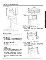
Page 7: ...people lift the range hood onto a covered surface 5 If the cabinet has a recessed bottom add wood filler strips on each side to fill in the space Install screws to attach filler strips in the loca tions shown in the illustration at the top of the next column NOTE All the screw locations must be measured from the cabinet s centerline Wood filler strips recessed cabinet bottoms only Cabinet bottom W...

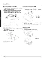
Page 8: ...ening on the underside of the cabinet top 1 Draw a centerline on the underside of the top of the cabinet 2 Draw a line 37 8 9 7 cm from the back wall on the underside of the top of the cabinet Make sure the line intersects with the line you drew in Step 1 3 Where the two lines intersect use a compass or a circle template to draw a 6 15 2 cm circle 4 With the circle you drew as a guide use a saber ...

Page 9: ...he range hood and secure it with the 4 4 2 x 8 mm screws A B B C A Range hood canopy inside back B 4 2 x 8 mm screws 4 C Rear blower motor mounting bracket assembly 6 Install the blower motor onto the rear motor mounting bracket included with the range hood Engage the motor mounting tabs with the keyhole slots in the rear mounting bracket and push down to secure Install the 4 screws removed previo...

Page 10: ...he top vent knockout 2 Attach the round vent transition damper using 2 3 5x9 5 mm vent tran sition mounting screws 3 Remove the tape from the damper flap A B C A Top round vent transition B Top round vent transition mounting screws 2 C Top vent knockout Installation Mounting the Range Hood on the Wall 1 Fix the wiring conduit of the hood 2 Slide the hood back against the wall Tighten the mounting ...

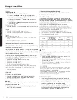
Page 11: ...as blown Disconnect the power and check the wiring connections NOTE To get the most efficient use from your new range hood read the Range Hood Care section Range Hood Description The range hood is designed to remove smoke cooking vapors and odors from the cooktop area For best results start the hood before cooking and allow it to operate several minutes after cooking to clear all smoke and odors f...

Page 12: ...d cook top have been paired To turn the function on press the Auto Connectivity button To turn the function off and disconnect the hood and cooktop press the Auto Connectivity button again 1 Press the Auto Connectivity button to activate the function 2 The hood will turn on off automatically in conjunction with the cooktop 3 Press again to deactivate the function Image e ote Control a n art in Aut...

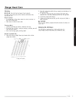
Page 13: ...el baffle filter 1 Remove the filter by pulling the spring release handle and then pulling down the filter A A Spring release handle 2 Wash the stainless steel baffle filter as needed in a dishwasher or hot detergent solution 3 To reinstall the filter first make sure the spring release handle is toward the front Insert the stainless steel filter into the upper track 4 Push in the spring release ha...

Page 14: ...ystems utilities services parts supplies accessories applications installations repairs external wiring or connectors not supplied or authorized by SAMSUNG which damage this product or result in service problems incorrect electrical line voltage fluctuations and surges customer adjustments and failure to follow operating instructions cleaning maintenance and environmental instruc tions that are co...

Page 15: ...allations repairs external wiring or connectors not supplied or authorized by SAMSUNG which damage this product or result in service problems incorrect electrical line voltage fluctuations and surges customer adjustments and failure to follow operating instructions cleaning maintenance and environmental instruc tions that are covered and prescribed in the instruction book problems caused by pest i...

Reviews: