104
4. Troubleshooting
This document can not be used without Samsung’s authorization.
4-6 Electrical Malfunction (Ver.01)
Troubleshooting (Wi-Fi connection)
Step 1 .
- Check whether display showed
• If display showed icon, check to ‘Samsung Connect’ app .
Delete and re-install the app . And then, try again
(Follow manual instruction for Samsung Connect app) .
• If display is not show icon, check to home network .
• If home network is ok, follow to step 2 .
• If home network have problem, contact home network service center .
TP6X Wi-Fi Module : use “Samsung Smart Home app”
ARTIK051 PF#3 Wi-Fi Module : use “Samsung Connect app”
Step 2 .
- Check communication between wi-fi module and PCB DISPLAY.
a) Press keepwarm and Num3 at the same time .
Display will show Project Name, Main PCB Ver(H)/DISPLAY PCB ver(P)/SUB PCB Ver(C)/
Touch PCB Ver(tou)/Network PCB ver .(n)/yymmdd
• If network version is ordinarily showed, try to use Smart Control feature again .
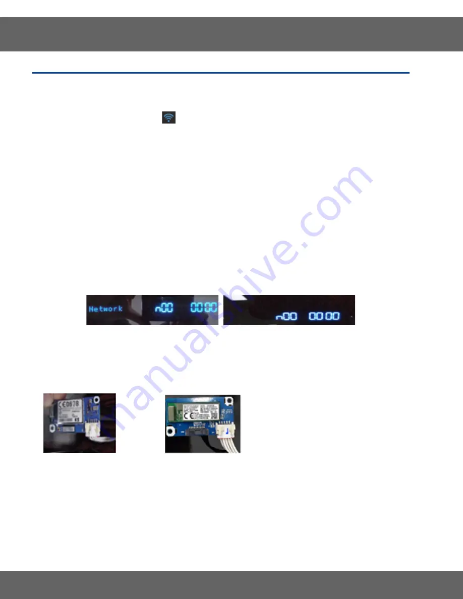
• If network version is showed as like below, check to wi-fi module. (2-b)
VFD DISPLAY
LED DISPLAY
b) Remove the wi-fi module (see page 3-33 Wi-Fi PCB, removing the wi-fi module for the procedure).
Check input voltage on wi-fi module. (12V)
• If input voltage is ok, replace wi-fi module.
• If input voltage have problem, check to connector of wire and sub pcb . (2-c)
4709-002627, ARTIK051 PF#3 Wi-Fi
4709-002577, TP6X Wi-Fi
Pin 4 : GND
Pin 5 : 12VDC
c) Remove the cover back main wire
(see page 3-2 removing the Rear Cover Panel .)
• If connection of wire is ok, check to next step (2-d)
• If connection of wire have problem, re-connect and try Smart Control feature again .
d) Remove the sub pcb (see page 3-5 removing sub pcb for the procedure) .
Check whether connector of wire is fully and correctly inserted . (CN270)
And then, check input voltage on sub pcb . (12V)
• If input voltage is ok, replace wi-fi module.
• If input voltage have problem, replace sub pcb .


