background image

57

4. Troubleshooting

4-2 Failure Display Codes

Oven Sensor information

Information code

Meaning

Solution

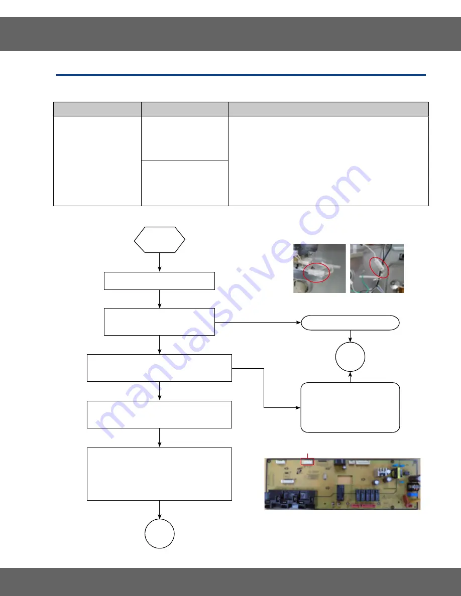
C-20

Oven sensor opened

(over 2950Ω)

1 .  

Disconnect power . Open the back cover . 

Disconnect sensor harness from control Measure sensor 

resistance :1080Ω at the room temperature


→ If there are any problems, replace oven sensor.

2 .  

If no problem with the oven sensor is found, Please check 

for damaged terminal or wire on harness .

3 .  

Check resistance of oven sensor connector on Main PCB 

(Normal:2850Ω)

Oven sensor shorted .

(Under 930Ω)

“C-20”

Disconnect power .

Measure sensor resistance .

(1080Ω at the room temperature)

Check the connecting condition of harness .

(Oven sensor and CNS301 of Main PCB)

Measure resistance of connector CNS301

of Main PCB. (Nomal : 2850Ω)

Check for damaged connectors, board 

pattern, soldered joins or components related 

to oven sensor on Main PCB, and repair them 

or replace Main PCB according to case .

END

Replace oven sensor .

END

* Reconnect .
*  Repair damaged harness 

replace .

oven sensor

PCB MAIN

CNS301

Summary of Contents for NX58M6850S Series

Page 1: ...ESTANDING GASRANGES 1 Precautions 2 Specifications 3 Disassembly and Reassembly 4 Troubleshooting 5 Wiring Diagrams 6 Schematic Diagrams 7 PCB Diagrams GAS RANGES CONTENTS MODELS AND MODEL CODES NX58M6850S ...

Page 2: ...sy Door Latch 28 3 13 Replacing the Door Plunger 29 3 14 Replacing the Door Plunger 30 3 15 Replacing the Assy Lamp Bulb 31 3 16 Replacing the Sensor Thermistor Upper Lower 32 3 17 Removing Air Supply Fan 33 3 18 Replacing the Gasket Door 34 3 19 Replacing the Oven Door Upper 35 3 20 Replacing the Handle Door Glass Inner Upper 37 3 21 Replacing the Oven Door Full 40 3 22 Replacing the Glass Inner ...

Page 3: ...57 4 3 Checkpoints before service request 70 4 4 PCBs Membrane 72 4 5 Trouble shooting 74 5 Wiring Diagram 92 5 1 Wiring Diagram 92 6 Schematic Diagrams 93 6 1 Schematic Diagram 93 7 PCB Diagrams 94 7 1 PCB Diagram NX58M6850S Main 94 7 2 PCB Diagram NX58M6850S 95 7 3 PCB Diagram NX58M6850S 96 ...

Page 4: ... to the appliance should be turned off and or disconnected when the range is being serviced or repaired WARNING To avoid risk of death or severe personal injury from electrical shock disconnect power before working on servicing the appliance To avoid risk of death severe personal injury or property damage from fire or explosion turn off the gas supply before working on servicing the appliance IF Y...

Page 5: ...become hot enough to cause burns During and after use do not touch or let clothing or other flammable materials contact burners heating element grates or interior surfaces of oven until they have had sufficient time to cool Other surfaces of the appliance may become hot enough to cause burns Among these surfaces are oven vent openings and surfaces near these openings oven doors and windows of oven...

Page 6: ...ferent sizes Select utensils having flat bottoms large enough to cover the surface burner flames The use of undersized utensils will expose a portion of the surface burner flames to direct contact and may result in ignition of clothing Proper relationship of utensil to burnerwill also improve efficiency NeverLeave Surface Burners Unattended at High Heat Settings Boilovers could ignite or extinguis...

Page 7: ... from electrical and gas supplies and have the appliance serviced by a licensed technician Use Care When Opening Door Let hot air or steam escape before you remove or replace food in the oven Do Not Heat Unopened Food Containers Buildup of pressure may cause container to burst and result in injury Keep Oven Vent Ducts Unobstructed The oven vent is located above the left rear surface unit This area...

Page 8: ...er Convenient front access drawer for storage of cooking utensils Five Open Port Surface Burners Simplest design promotes serviceability and clean ability BTU Ratings NG LP RF 16 000 12 500 RR 5 000 4 000 Center 9 500 7 500 LR 9 500 7 500 LF 15 000 11 500 Large Capacity Oven Provides cooking ease and necessary space for all recipes and meal items Flex Duo Oven Convection fan the rear of the oven c...

Page 9: ...C Variable Broil Low High Low 392 F 200 C High 464 F 240 C Low 392 F 200 C High 464 F 240 C Low 392 F 200 C High 464 F 240 C Low 392 F 200 C High 464 F 240 C Convection Bake 175 F 79 C 550 F 288 C 175 F 79 C 480 F 249 C 175 F 79 C 550 F 288 C 175 F 79 C 480 F 249 C Convection Roast 175 F 79 C 550 F 288 C 175 F 79 C 480 F 249 C 175 F 79 C 550 F 288 C 175 F 79 C 480 F 249 C Auto Oven Light Yes Yes Y...

Page 10: ...nuous grate Matte Black continuous grate Oven Convection Element Wattage Fan True Convection 900W Fan True Convection 900W Oven Capacity cu ft 5 8 5 8 Broiler Gas Gas Bake Burner 18 000 18 000 Broil Burner 13 500 13 500 Interior Light Watts Location 2 Incandescent 40W Back 2 Incandescent 40W Back of Oven Racks 3 3 of Rack Positions 7 7 Rack Finish Chrome Chrome Door Dual door Dual door Door Materi...

Page 11: ... 1 Application Dimensions Actual Oven Dimensions WxHxD 25 x 211 8 x19 25 x 211 8 x19 635 x 536 x 481 635 x 536 x 481 Usable Oven Dimensions WxHxD 23 29 32 x17 21 64 x 17 23 32 23 29 32 x17 21 64 x 17 23 32 607 x 440 x 450 607 x 440 x 450 Overall Dimensions WxHxD 2915 16 x 46 5 8 x 26 29 15 16 x 46 5 8 x 26 760 X1183 X 660 760 X1183 X 660 Shipping Dimensions WxHxD 331 16 x 50 5 8 x 30 5 16 331 16 x...

Page 12: ... 2 Specifications 2 3 Accessories Item Description Code No Quantity Assy Grate Side Coating DG94 00937A 2 Assy Grate Center Coating DG94 00938A 1 Rack Flat DG75 01001C 3 Assy Partition Flex DG94 00484A 1 ...

Page 13: ...ow to use Pictures Screw driver Use for assembly and disassembly of all screws Tubing Wrench Use for assembly and disassembly of tubing to the burner cup 7mm Vox Driver Use for assembly and disassembly of injector nozzles Cooktop Broil Bake burner 3 Disassembly and Reassembly ...

Page 14: ...m explosion fire or asphyxiation CAUTION When you work on the gas range be careful when handling sheet metal parts Sharp edges may be present and you can cut yourself if you are not careful Parts Explanation Photo Explanation Cover Wire LT RT Cover Wire LT Cover Wire RT 1 Turn off the electrical supply going to the range 2 Shut off the gas shut off valve in the gas supply line to the range 3 Pull ...

Page 15: ...place the four cover panels on the back of the range and secure each with the appropriate screws 8 Reconnect the gas supply line to the range if removed Open the main gas shut off valve and check for gas leaks 9 Plug in the range and orturn on the electrical supply to the range 10 Push the range back in place making sure to engage the anti tip bracket on the left rear leveling leg ...

Page 16: ...re not careful Parts Explanation Photo Explanation Assy Frame Cooktop ASSY GRATE 2 SIDE 1 CENTER BURNER CAP BURNER HEAD BURNER CUP 1 Turn off the electrical supply going to the range 2 Shut off the gas shut off valve in the gas supply line to the range 3 Lift off the three grates 4 Lift off the 5 burner caps and the 5 burner heads from the burner cups 5 Remove screws from the 5 burner cups Assy Fr...

Page 17: ...tings for leaks before operating the range Replace all panels before operating the range Failure to do so can result in death or personal injury from explosion fire or asphyxiation CAUTION When you work on the gas range be careful when handling sheet metal parts Sharp edges may be present and you can cut yourself if you are not careful Parts Explanation Photo Explanation ASSY PCB MAIN ASSY PCB MAI...

Page 18: ... Disassembly and Reassembly 3 4 Removing ASSY PCB Main Parts Explanation Photo Explanation ASSY PCB MAIN LED 4 Remove 3 screws of Main PCB 5 Separate Main PCB from Holder PCB 6 Separate LED from Holder PCB ...

Page 19: ...d fittings for leaks before operating the range Replace all panels before operating the range Failure to do so can result in death or personal injury from explosion fire or asphyxiation CAUTION When you work on the gas range be careful when handling sheet metal parts Sharp edges may be present and you can cut yourself if you are not careful Parts Explanation Photo Explanation ASSY PCB DISPLAY ASSY...

Page 20: ...ssembly and Reassembly 3 5 Removing ASSY PCB DISPLAY Parts Explanation Photo Explanation ASSY PCB DISPLAY 4 Remove 4 screws of the HOLDER PCB SUB 5 Remove 2 screws of the ASSY PCB SUB 6 Replace the ASSY PCB SUB ...

Page 21: ...re operating the range Replace all panels before operating the range Failure to do so can result in death or personal injury from explosion fire or asphyxiation CAUTION When you work on the gas range be careful when handling sheet metal parts Sharp edges may be present and you can cut yourself if you are not careful Parts Explanation Photo Explanation ASSY PCB SUB ASSY PCB SUB 1 Follow the step A ...

Page 22: ...heck all gas lines and fittings for leaks before operating the range Replace all panels before operating the range Failure to do so can result in death or personal injury from explosion fire or asphyxiation CAUTION When you work on the gas range be careful when handling sheet metal parts Sharp edges may be present and you can cut yourself if you are not careful Parts Explanation Photo Explanation ...

Page 23: ...ls before operating the range Failure to do so can result in death or personal injury from explosion fire or asphyxiation CAUTION When you work on the gas range be careful when handling sheet metal parts Sharp edges may be present and you can cut yourself if you are not careful Parts Explanation Photo Explanation COOLING FAN Cooling Fan Bracket Cooling Fan 1 Follow the steps in 3 2 2 Disconnect 2 ...

Page 24: ...sheet metal parts Sharp edges may be present and you can cut yourself if you are not careful Parts Explanation Photo Explanation Knob Pull the control knob straight off 1 Turn off the electrical supply going to the range 2 Shut off the gas shut off valve in the gas supply line to the range 3 Open the door or Remove it 4 Pull burner control knobs straight off to remove them from the valve shafts Ch...

Page 25: ...edges may be present and you can cut yourself if you are not careful Parts Explanation Photo Explanation Switch Ignition SWITCH IGNITION 1 Turn off the electrical supply going to the range 2 Shut off the gas shut off valve in the gas supply line to the range 3 Remove the ASSY FRAME COOKTOP knob and the chassis manifold panel 4 Place a finger behind each side of the switch ignition and pull it stra...

Page 26: ... on the gas range be careful when handling sheet metal parts Sharp edges may be present and you can cut yourself if you are not careful Parts Explanation Photo Explanation Burner cup Locking Clip Electrode Burner Cup Tube Injector 1 Turn off the electrical supply going to the range 2 Shut off the gas shut off valve in the gas supply line to the range 3 Remove the frame cooktop 4 Using a tubing wre...

Page 27: ...module 7 To remove the gas orifice place the burner cup in a vise and remove the orifice with a 9 32 inch socket wrench 8 When service is complete Install the gas orifice in the new burner cup NOTE The new burner cup must be the same size as the one removed 9 Reconnect the electrode to the new burner cup and replace the burner cup in the reverse order 3 11 Replacing the BurnerCup ...

Page 28: ...elf if you are not careful Parts Explanation Photo Explanation Assy Tube Manifold 1 Turn off the electrical supply going to the range 2 Shut off the gas shut off valve in the gas supply line to the range 3 Remove the oven door cooktop control knob and chassis manifold panel 4 Remove the ASSY tube manifold using a tubing wrench Assy Door Latch ASSY Door Latch Bracket Latch sub 5 Remove 2 screws fro...

Page 29: ...s and fittings for leaks before operating the range Replace all panels before operating the range Failure to do so can result in death or personal injury from explosion fire or asphyxiation CAUTION When you work on the gas range be careful when handling sheet metal parts Sharp edges may be present and you can cut yourself if you are not careful Parts Explanation Photo Explanation Door Plunger 1 Fo...

Page 30: ...ew of the shield and separate the shield 6 Disconnect the wire to the door plunger 7 Carefullypull outthe doorplungerfromthe upperright cornerofthe cavityfront Gently graspthe plungerwith pliers andworkfrom sideto sidewhile pulling 8 Replacewith the doorplunger reconnect the wires in theiroriginal positions and reinstall plungerin the oven frame ...

Page 31: ...ire or asphyxiation CAUTION When you work on the gas range be careful when handling sheet metal parts Sharp edges may be present and you can cut yourself if you are not careful Parts Explanation Photo Explanation Assy Lamp Bulb 1 Turn off the electrical supply going to the range 2 Shut off the gas shut off valve in the gas supply line to the range 3 Remove the rear cover panel 4 Open the oven door...

Page 32: ...k on the gas range be careful when handling sheet metal parts Sharp edges may be present and you can cut yourself if you are not careful Parts Explanation Photo Explanation Sensor Thermistor Upper Lower SENSOR THERMISTOR Upper Lower CONNECTOR 1 Turn off the electrical supply going to the range 2 Shut off the gas shut off valve in the gas supply line to the range 3 Open the oven door and remove the...

Page 33: ...s before operating the range Replace all panels before operating the range Failure to do so can result in death or personal injury from explosion fire or asphyxiation CAUTION When you work on the gas range be careful when handling sheet metal parts Sharp edges may be present and you can cut yourself if you are not careful Parts Explanation Photo Explanation Air Supply Fan Air Supply Fan 1 Follow t...

Page 34: ...n the gas range be careful when handling sheet metal parts Sharp edges may be present and you can cut yourself if you are not careful Parts Explanation Photo Explanation Gasket Door 1 Open the oven doorto its fully down position 2 Pull the ends of the gasket out of the liner holes 3 Pull the oven door gasket clips out of the holes until all of the clips are removed 4 When the service is complete I...

Page 35: ...all panels before operating the range Failure to do so can result in death or personal injury from explosion fire or asphyxiation CAUTION When you work on the gas range be careful when handling sheet metal parts Sharp edges may be present and you can cut yourself if you are not careful Parts Explanation Photo Explanation OVEN DOOR UPPER To remove Oven Door Upper 1 Fully open the doorwith pressing ...

Page 36: ... OVEN DOOR UPPER Locked To replace door 1 Firmly grasp both sides of the door at the top position 2 Fully open the door If the doorwill not fully open it means that the indentation is not seated correctly in the bottom edge of the slot Push the hinge locks up to the locked position 3 Close the oven door ...

Page 37: ...d fittings for leaks before operating the range Replace all panels before operating the range Failure to do so can result in death or personal injury from explosion fire or asphyxiation CAUTION When you work on the gas range be careful when handling sheet metal parts Sharp edges may be present and you can cut yourself if you are not careful Parts Explanation Photo Explanation HANDLE DOOR 1 Remove ...

Page 38: ...ly and Reassembly 3 20 Replacing the Handle Door Glass Inner Upper Parts Explanation Photo Explanation HANDLE DOOR 5 Lift the door rear assembly off the front assembly and set it aside 6 Remove 2 spacers and 2 screws ...

Page 39: ...to remove Handle Door GLASS INNER Back side of this point ASSY PCB SUB 1 Remove 4 screws to remove the Glass inner sub 2 Remove 6 screws to remove the Assy Hinge Up 3 Remove 7screws or remove Baffle Door 4 Remove 8 screws to remove Baffle Door and take out the Glass Inner assembly 5 Unfold 2 flanges of Cover Frame Inner Glass and take out Glass Inner ...

Page 40: ...rating the range Replace all panels before operating the range Failure to do so can result in death or personal injury from explosion fire or asphyxiation CAUTION When you work on the gas range be careful when handling sheet metal parts Sharp edges may be present and you can cut yourself if you are not careful Parts Explanation Photo Explanation OVEN DOOR FULL 1 Fully open the door 2 Pull the hing...

Page 41: ...Explanation OVEN DOOR FULL 1 Firmly grasp both sides of the door at the top position 2 Fully open the door If the door will not fully open it means that the indentation is not seated correctly in the bottom edge of the slot Push the hinge locks up to the locked position 3 Close the oven door ...

Page 42: ...l gas lines and fittings for leaks before operating the range Replace all panels before operating the range Failure to do so can result in death or personal injury from explosion fire or asphyxiation CAUTION When you work on the gas range be careful when handling sheet metal parts Sharp edges may be present and you can cut yourself if you are not careful Parts Explanation Photo Explanation OVEN DO...

Page 43: ...Glass Inner Full Door Parts Explanation Photo Explanation OVEN DOOR FULL Glass Inner assembly 4 Remove the 7 screws to remove the BAFFLE DOOR LOW 5 Take out the Glass Inner assembly 6 Unfold 2 flanges of Cover Frame Inner Glass to taking out Glass Inner ...

Page 44: ...as supply line to the range 3 Open the warming drawerto the fully opened position 4 Locate glide lever on each side of drawer Push down on the left glide lever and pull up on the right glide leverwhile pulling the drawerthe rest of the way out 5 To install place the ends of the drawer side rails into the ends of the drawer glide rails 6 Push in the drawerto close the drawer and snap the glide leve...

Page 45: ...Cover Back Main Wire 2 Disconnect the wires orthe connector of the HSI Identify and mark the two wires going to HSI 3 Remove 2 screws of Cover Broil and separate the Cover Broil Bracket H S I WIRE 4 Remove 1 screw of bracket HSI wire and separate the bracket HSI wire 5 Remove 4 screws of bracket broil spreaderto top of oven 6 Support the burner broil with one hand remove 2 screw supporting the bur...

Page 46: ...sphyxiation CAUTION When you work on the gas range be careful when handling sheet metal parts Sharp edges may be present and you can cut yourself if you are not careful Parts Explanation Photo Explanation Hot Surface Ignitor HSI 1 To replace the HSI of the burner broil Remove 2 screws assembled to HSI Nozzle Broil Burner Remove the gas nozzle 1 To replace the nozzle broil burner Remove the gas noz...

Page 47: ...be present and you can cut yourself if you are not careful Parts Explanation Photo Explanation Burner Bake 1 Turn off the electrical supply going to the range 2 Shut off the gas shut off valve in the gas supply line to the range 3 Open the oven door and remove the racks from inside the oven 4 Pull on the wires orthe connector until the wire connector appears from the back wall of the warming drawe...

Page 48: ...fire or asphyxiation CAUTION When you work on the gas range be careful when handling sheet metal parts Sharp edges may be present and you can cut yourself if you are not careful Parts Explanation Photo Explanation Hot Surface Ignitor HSI HSI 1 To replace the burner bake HSI Remove 2 screws assembled to HSI Nozzle Bake Burner HOLDER NOZZLE 1 To replace the nozzle bake burner Remove the gas orifice ...

Page 49: ...he racks from inside the oven 4 Remove 2 screws and the interior cover casing from the back wall of the oven cavity NOTE When you install the uppercover casing please referto the pictures 5 Remove the fan nut fan blade from the motor convection shaft The convection nuts have CCW CW threads to remove each nut NOTE Do not fasten fan nuts too tight 6 Unbend the bracket of the back main to the rear of...

Page 50: ...ing the range Failure to do so can result in death or personal injury from explosion fire or asphyxiation CAUTION When you work on the gas range be careful when handling sheet metal parts Sharp edges may be present and you can cut yourself if you are not careful Parts Explanation Photo Explanation Heater Convection 1 Follow the Step in 3 2 2 To remove convection heater disconnect wires or connecto...

Page 51: ...on fire or asphyxiation CAUTION When you work on the gas range be careful when handling sheet metal parts Sharp edges may be present and you can cut yourself if you are not careful Parts Explanation Photo Explanation Assy Safety Valve Support Regulator REAR 1 Turn off the electrical supply going to the range 2 Shut off the gas shut off valve in the gas supply line to the range 3 Remove the regulat...

Page 52: ...r Bake Nozzle from the back wall of the storage drawer opening 8 Install the new ASSY VALVE SAFETY and Holder Nozzle Bake on the back wall of the storage drawerwith 7 screws 9 Reconnect wire connectors in their original positions NOTE Check all gas lines and fittings for leaks before operation WARNING Cross wiring the wires to the gas control valve creates an explosion hazard that can result in de...

Page 53: ...ION FIRE AND ASPHYXIATION HAZARD Shut off the gas supply to the range before servicing Check all gas lines and fittings for leaks before operating the range Replace all panels before operating the range Failure to do so can result in death or personal injury from explosion fire or asphyxiation Parts Explanation Photo Explanation Assy Power Cord Cover Ground Wire Housing 1 Turn off the electrical s...

Page 54: ...rk on the gas range be careful when handling sheet metal parts Sharp edges may be present and you can cut yourself if you are not careful WARNING EXPLOSION FIRE AND ASPHYXIATION HAZARD Shut off the gas supply to the range before servicing Check all gas lines and fittings for leaks before operating the range Replace all panels before operating the range Failure to do so can result in death or perso...

Page 55: ...i PCB Inside Outside Protect wire connector The direction reference 1 Open the drawer and remove 1 screw of Wi Fi holder PCB 2 Push the hook of cover PCB and open the cover PCB 3 Pull out the Wi Fi PCB and disconnect wire connectorfrom the Wi Fi PCB 4 Replace the Wi Fi PCB 4709 002627 ARTIK051 PF 3 Wi Fi 4709 002577 TP6X Wi Fi Pin 4 GND Pin 5 12VDC ...

Page 56: ... the Clock pad 2 Press the number pads 1 2 3 and 4 Make sure the Timer is turned OFF 3 Press the Start SET pad 4 Press the Clock and the 1 number pads at the same time for 3 seconds Information codes are displayed 5 Press the 0 number pad to display the latest 5 Information codes But if the power is interrupted and the oven turns off the stored Information codes are deleted 6 Press the OFF Clear p...

Page 57: ...erminal orwire on harness 3 Check resistance of oven sensorconnectoron Main PCB Normal 2850Ω Oven sensorshorted Under930Ω C 20 Disconnect power Measure sensorresistance 1080Ω at the room temperature Check the connecting condition of harness Oven sensorand CNS301 of Main PCB Measure resistance of connectorCNS301 of Main PCB Nomal 2850Ω Check fordamaged connectors board pattern soldered joins orcomp...

Page 58: ...sensor 2 Check the resistance of each broil bake and convection heater 3 Check whetherDLB Broil Bake and Convection heater relay are working normally 4 Make sure all connectors on Main PCB are plugged in correctly 5 Check the resistance of oven sensorconnectoron Main PCB Normal 2850Ω 6 Check whether divider switch is in OFF position with divider inserted If divider switch is Off with divider inser...

Page 59: ...Reconnect afterreplacing the oven sensor Replace Main PCB Repairany damaged area Check the DLB Bake and Broil relay Normal Ω Check forany damaged components orparts of PCB Check harness connectorCNS301 on Main PCB if it is plugged in correctly Replace Main PCB END Replace orrepairthe harness END END Ok Ok Ok Ok No No No Main PCB C HeaterRelay Source Relay Bake Relay Broil Relay CNS301 ...

Page 60: ... PCB SensorOpened 1 Disconnect electrical Powerto the range Remove the upperrearcoverpanel Measure the sensorresistance PCB sensor 3900Ω at the room temperature Oven sensor 1080Ω at the room temperature 2 Replace the PCB PCB SensorShorted Oven SensorError ...

Page 61: ...Check the oven sensorharness connections at the PCB Replace orreconnect the oven sensor Repairorreplace the PCB Repairany damaged area Measure PCB sensorresistance 3900Ω at the room temperature Make sure the harness connectors are completely seated in the CNP207 CNP208 and CNP209 terminals on the PCB END END Ok Ok END Ok No No ...

Page 62: ...62 4 Troubleshooting Failure Code Cause Solution C 31 PCB temperature too high 1 Disconnect power and remove the PCB 2 Replace the PCB Safety Error ...

Page 63: ...63 4 Troubleshooting Disconnect powerand remove the PCB Replace the PCB C 31 END Ok Ok ...

Page 64: ...on Sub PCB 2 Check Sub PCB keypad connectorforshorts 3 If no problems are found with Sub PCB keypad connector replace the Sub PCB Sub PCB CN701 C d0 Disconnect power Take out keypad from the Sub PCB Check connectorCN701 pins on Sub PCB for shorts Check keypad membrane forshorts No No Yes END END Replace orrepairMembrane Repairany shorts ordamaged areas on Sub PCB ...

Page 65: ...lly C d1 Disconnect power Disconnect harness connected to a Lock motor Doorlock position switch check dooropen com NO Measure resistance of Lock motorCoil 1750 1850Ω at the room temperature Check whethervoltage AC120V is supplied to lock motorand motoroperation Check whetherwire harness is connected normally into CNS300 on main PCB Measure resistance of CNS300 on main pcb COM NO at the room temper...

Page 66: ...emove a divider in single mode 2 Please check divider sensing S W dC Is unit in Single cavity cooking mode Is unit in double cavity cooking mode Please check dividersensing switch Please connect wire harness Please insert divider Please take out divider Please change dividersensing switch Is switch harness disconnected END No No No Yes Yes Yes ...

Page 67: ...b Main CNS401 Sub DISPLAY CN200 Main CN304 Sub FAN CONTROL CN500 2 Check software version by pressing Keep Warm key and 3 on number pad simultaneously for 3 seconds Main 1204 Sub DISPLAY 1204 C F0 Check software version Main 1204 Sub display 1204 Sub fan cntrol 1201 Is the wire harness disconnected Connect the wire harness completely Perform the operation again and check if it is working property ...

Page 68: ...re version by pressing Keep Warm key and 3 on number pad simultaneously for 3 seconds Main 1204 Touch 02 C F2 Check software version Main 1204 Touch 02 Is the wire harness disconnected Connect the wire harness completely Perform the operation again and check if it is working property Replace the PCB Replace the PCB END Yes Yes No No ...

Page 69: ...he voltage of CN200 PIN 1 3 4 6 Propervoltage range 10VDC 14VDC Upper Cooling motor Lower Airintake motor Operate Self Clean Within 2min END C A2 Start Self Clean Change BLDC motor Check displayed information after2 min of running self clean Is the wire harness connected Check voltage BLDC Fan PCB Propervoltage range 10VDC 14VDC Cooling FAN PIN 5 7 AirIntake motor PIN1 4 Yes Yes Connect to wire ha...

Page 70: ...module Replace the electrode in case of broken electrode orcut off wire Replace the spark module Oven temperature is increasing too slow Check whetherharness is connected to Broil Bake and convection heater Disconnected orLoosen Repairand replace harness Measure the resistance at the terminals of the hot surface igniter 345Ω Replace the hot surface ignitor Measure the amperage of Safetyvalve 3 3 3...

Page 71: ...ad is being touched Check the condition of the buzzeron Sub PCB and forshorted oropened areas Replace orrepairSub PCB Cooktop flame with LP is extraordinary short Check the cap of regulator Remove the cap of regulatorand mount it again upside down Replace the regulator Cooktop flame with LP is extraordinary long severe yellow flame Check the injectornozzle Replace the NG injectornozzle to LP injec...

Page 72: ...72 4 Troubleshooting 4 4 PCBs Membrane Pictures of PCB and Membrane PCB Front Back Membrane Bracket Assembly Front Back ...

Page 73: ...lock and timer operation by touching the membrane on the control panel 2 The marking on the front of membrane acts as a guide forwhere the panel should be touched to select and program that function If membrane touch control stops working replace the membrane and membrane bracket 3 Membrane tail connects the Membrane Keypad to PCB NX58M6850S Carbon touch Keypad ...

Page 74: ...connected Insert the powercord END No Ok Ok Ok Check the voltage of the Powercord connectorhousing 120V Replace the Powercord END No Check the voltage of the Wire harness A housing CNP100 Replace the Wire harness A END No Check the voltage of the PCB connector CNP100 Replace the PCB END No CNP100 ...

Page 75: ...are notworking properly Make sure the Doorlock feature is not turned on END Make sure the Sabbath feature is not turned on Press the TimerOn Off and Clock forthree ormore seconds at the same time No Press the Start Set keypad forthree ormore seconds No OK OK Replace the membrane END END CN701 Sub PCB ...

Page 76: ...76 4 Troubleshooting Trouble shooting Buzzerdoes not beep when keypad is touched Buzzerdoes not beepwhen keypad is touched END Faulty buzzeron PCB Ok Ok Replace the PCB ...

Page 77: ...END No Ok Ok Yes Ok Ok Check Gas pressure regulatorto make sure gas is flowing through it Check the manifold pipe damaged ornot Check forgas supply to the surface burnercontrol manifold No Replace the Manifold Pipe Fully open the gas supplyvalve Is the GPR shut off leverin the open position Replace the GPR Crimped orbroken gas supply line to the manifold Replace the damaged gas line ...

Page 78: ...rnerswill light END Make sure there is power to the range Make sure the gas supplyvalve to the range is open Check each surface burnerterminal on the spark module forvoltage No No No Ok Ok Ok Replace the PCB Open the gas supplyvalve Replace the faulty spark module Plug in the powercord and or reset the circuit breakerforthe range ...

Page 79: ...terminals of ignition switch housing when knob is set to LITE Check fora dirty surface of the burnerorifice Check the spark from the electrode when it its turned to LITE No No No No No No Change the Ignition switch Change the Electrode Assemble the burnerhead and cap on the right position Clean the surface of burnerorifice orreplace the orifice Check thevoltage of the Spark module connector 120V R...

Page 80: ...rawer are properly assembled 2 points Check the AssyValve Cooktop tube are properly assembled 11points Check fora crimped of broken gas pipe No No No No Ok Ok Ok Ok Assemble the gas pipes correctly Assemble the AssyValve Cooktop tubes correctly Replace the damage gas pipe Assemble the gas pipes on the right position AssyValve Cooktop 11 Points Drawer 2 Points Back Side 4 Points ...

Page 81: ...he orifice nozzle Adjust the airshutteropening LP NG Place the burnerheads and caps properly Applythe right direction of the orifice Burner orifice sizes and output rating LP Gas Propane 10 in WCP Burner orifice sizes and output rating Natural Gas 5 in WCP Burner Location BTU Rate Orifice Size mm Burner Location BTU Rate Orifice Size mm RF 12 500 1 06 RF 16 000 1 92 LF 11 500 1 04 LF 15 000 1 78 R...

Page 82: ...o big orsmall Check the orifice nozzle diameter Check the orifice direction at GPR END END END No No Ok Ok Replace the orifice nozzle LP NG Reverse the direction of the orifice Upside down Trouble shooting Flame size is too big ortoo small ...

Page 83: ...whetherthe gas is properly supplied Check the current of the safetyvalve terminal 3 3 3 6A Checkwhetherthe Hot surface ignitor HSI isworking correctly No Ok Ok Ok Ok No No No No Open the gas valve Replace the Safetyvalve Replace the PCB Replace the HSI Check the voltage 120V at the DLB Bake DLB Broil Check the resistance of HSI 40 400Ω END Safety valve terminal ...

Page 84: ...ers to check whetherthe gas is properly supplied Check the voltage 120V of the PCB DLB Bake DLB Broil Check the current of the safetyvalve terminal 3 3 3 6A Check whetherthe Hot surface ignitor HSI is working correctly No Ok Ok Ok Ok No No No No Open the gas valve Replace the PCB Replace the Safetyvalve Replace the PCB Check the resistance of HSI 40 400Ω END ...

Page 85: ...PCB Faulty broil bake ignitor DLB orSource control relay RY201 RY204 Replace the PCB Replace with properly sized burnerorifices NG LP Broil 1 64 1 02 Bake 1 90 1 15 NOTE High altitude orifice kits are available Replace the PCB No No Yes Yes Ok Ok Ok END END PCBCommunication connector CNS401 Membraneconnector CNS302 DLBrelay RY201 C Heaterrelay RY202 BroilIN OUT CNP207 CNP208 Lamp Motor CNP210 CNP2...

Page 86: ...en burner orifices Check forcrimped orbroken gas lines to the lowerorupperoven burner Replace the faulty lowerand or upperoven burner END END END END END Fully open the gas supplyvalve Adjust the burnerairshuttersetting Replace the GPR Replace the damage gas line Is the GPR shut off leverin the open position Clean and orreplace the lower and upperoven burnerorifices Replace the faulty lowerand or ...

Page 87: ...hen the oven Temperature reaches 650 343 in any cooking function except self clean Check the resistance of the oven temperature sensor Normal 1080Ω END END Replace the temperature sensor Replace the temperature sensor No No Ok Ok Ok END Trouble shooting Oven overheating in all cooking modes oven sensor ...

Page 88: ...n lamp and source control relays RY608 RY601 Measure the resistance across the light ballast socket terminals Normal Ω END END END END Press and hold the lock keypad button forthree or more seconds to unlock the unit Remove oven lamp cover and oven light bulb If burned out replace with a 40W appliance bulb Reconnect securely or replace damaged wire harness Replace the oven light ballast socket No ...

Page 89: ...value of Motor terminal aftertaking off harness from Motor 25Ω 7 Afterpressing the Conv Bake key wait for10mins Measure Voltage of Motor s terminal 120V END END END END Replace the Motor Replace the Wire harness A Replace the PCB Measure the voltage of Relay RY207 RY210 at PCB 120V No No No Ok Ok Ok RY210 RY207 ...

Page 90: ...rsion is showed as like below check the wi fi module 2 b VFD DISPLAY LED DISPLAY b Remove the wi fi module see page 3 33 Wi Fi PCB removing the wi fi module for the procedure Check input voltage on wi fi module 12V If input voltage is ok replace wi fi module If input voltage is not present check to connector of wire and sub pcb 2 c Pin 4 GND Pin 5 12VDC c Remove the cover back main wire see page 3...

Page 91: ...check the wi fi module 2 b VFD DISPLAY LED DISPLAY b Remove the wi fi module see page 3 33 Wi Fi PCB removing the wi fi module for the procedure Check input voltage on wi fi module 12V If input voltage is ok replace wi fi module If input voltage is not present check to connector of wire and sub pcb 2 c 4709 002627 ARTIK051 PF 3 Wi Fi 4709 002577 TP6X Wi Fi Pin 4 GND Pin 5 12VDC c Remove the cover ...

Page 92: ...5 Wiring Diagram 92 5 1 Wiring Diagram 5 Wiring Diagram NOTE 1 Input power AC120 V 60 Hz COLOR RED BRN ORG YEL YELLOW ORANGE BROWN RED GRN GREEN BLK BLACK YELLOW GREEN Y G BLUE GRAY WHITE BLU GRY WHT ...

Page 93: ...6 Schematic Diagrams 93 6 1 Schematic Diagram 6 Schematic Diagrams SCHEMATIS DIAGRAM NX58M6850S ...

Page 94: ... is the connector that micom program down load to MAIN PCB 10 CNS300 SWTICH This is the connector that connects the door sensing lock switch with the divider switch 11 RY201 DLB RELAY Circuit is designed to have bake broil Conv heater relay worked after DLB relay is being worked by double line break 12 RY202 C HEATER RELAY This the relay that controls the Conv heater operation 13 RY203 BAKE REALY ...

Page 95: ...E_IN_VE PBA 3 CN200 Fan Control Connector This is connectorwhich is connected with FAN to control 4 CN700 Cooling Fan TCO Connector This is connected with cooling FAN TCO 5 CN450 Micom Writing Connector This is connector for writing Micom 6 CN800 HASS Connector This is connector for HASS Smart Test 7 CN500 Main Communication Connector This is connectorwhich is connected with Main PCB to communicat...

Page 96: ... SUB Control Connector This is connectorwhich is connected with BLDC FAN SUB PBA For GAS Model 4 CN220 LED Module Connector This is connector for LED Display Module 5 CN270 WIFI Connector This is connectorwhich is connected with WIFI Module 6 CN601 Knob sensing Connector This is connector to check knob ON OFF 7 CN700 Touch Download Connector This is connector to download program for touch IC 8 CN7...

Reviews: