4- 5
4.
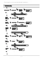
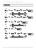
Troubleshooting
3) System Diagnosis
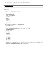
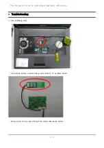
(1) System Diagnostics Card
The Diagnostics Card shows the system operations during the POST (Power On Self Test) in a
2 digit hexadecimal number by connecting the cable to the 10 pin connector below the PCMCIA slot
after separating the Top part. The card is used to evaluate the reason for the malfunction without
disassembling the system when the system malfunctions and to test if the system operates normally
after replacing a defective FRU.
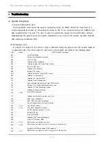
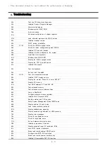
(2) Debugging Code
In general, if a defect of the circuit or part is detected during the system test, the system stops at
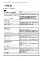
a particular code. The error codes for each part of the system are listed in the following table.
Code
Beeps
POST Routine Description
02h
Verify Real Mode
03h
Disable Non-Maskable Interrupt
04h
Get CPU type
06h
Initialize system hardware
08h
Initialize chipset with initial POST values
09h
Set IN POST flag
0Ah
Initialize CPU registers
0Bh
Enable CPU cache
0Ch
Initialize caches to initial POST values
0Eh
Initialize I/O component
0Fh
Initialize the local bus IDE
10h
Initialize Power Management
11h
Load alternate registers with initial POST values
12h
Restore CPU control word during warm boot
13h
Initialize PCI Bus Mastering devices
14h
Initialize keyboard controller
16h
1-2-2-3
BIOS ROM checksum
17h
Initialize cache before memory auto size
18h
8254 timer initialization
1Ah
8237 DMA controller initialization
1Ch
Reset Programmable Interrupt Controller
20h
1-3-1-1
Test DRAM refresh
22h
1-3-1-3
Test 8742 Keyboard Controlle
24h
Set ES segment register to 4 GB
26h
Enable A20 line
28h
Auto size DRAM
29h
Initialize POST Memory Manager
2Ah
Clear 512 KB base RAM
2Ch
1-3-4-1
RAM failure on address line xxxx*
2Eh
1-3-4-3
RAM failure on data bits xxxx* of low byte of memory bus
2Fh
Enable cache before system BIOS shadow
30h
1-4-1-1
RAM failure on data bits xxxx* of high byte of memory bus
- This document cannot be used without the authorization of Samsung -

