5 Troubleshooting
PN15VT/VO
PN15HT/HO
5-3
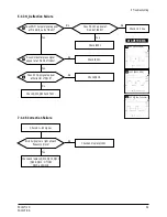
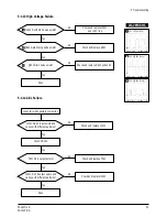
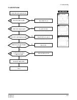
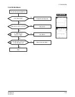
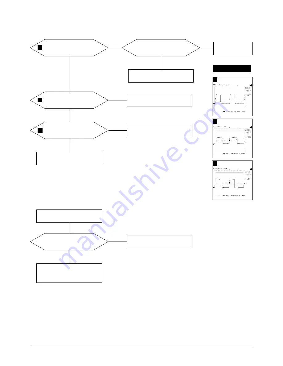
5-1-3 H_Deflection Failure
Does Horizontal pluse signal
appear at at Pin 26 of IC401?
Check IC401.
Yes
No
Does 20 Vp-p signal appear
at Collector of Q418?
Check Q418.
No
No
Check Q402, Q404 and T401.
WAVEFORMS
4
3
5.00 V (IC401, #28)
4
1.00V (IC401, #26)
5
5.00 V (Q418, Collector)
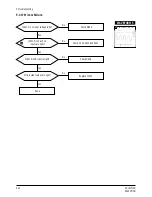
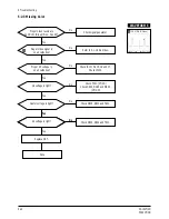
Does PWM output signal appear
at Pin 28 (B_out) of IC401?
Check IC401.
Check 12 V line.
Yes
No
Does DC 12V appear at
Pin 29 of IC401?
Yes
No
3
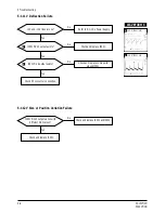
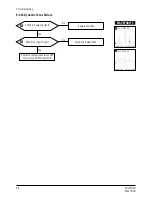
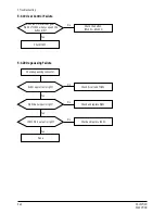
7-1-4 S Correction Failure
S1~S3 signals are right at each
frequency block?
Check S1 ~ S3 signal.
Check and replace Q404, Q410, Q411,
(Q409, Q414 : HT/HO)
Q415, and Q416.
Yes
Check and replace IC201.
No
5
Summary of Contents for PN15VT / VO
Page 7: ...2 Product Specifications 2 4 PN15VT VO PN15HT HO Memo...
Page 17: ...Memo 4 Alignment and Adjustments 4 8 PN15VT VO PN15HT HO...
Page 36: ...PN15VT VO PN15HT HO 6 1 6 Exploded View and Parts List 6 1 PN15VT HT...
Page 37: ...6 2 PN15VO HO 6 Exploded View Parts List 6 2 PN15VT VO PN15HT HO...
Page 38: ...6 Exploded View and Parts List 6 1 1 Front Cover CRT Ass y PN15VT HT PN15VT VO PN15HT HO 6 3...
Page 39: ...6 1 2 Chassis Stand Ass y PN15VT HT 6 Exploded View Parts List 6 4 PN15VT VO PN15HT HO...
Page 40: ...6 1 3 Rear Cover Ass y PN15VT HT 6 Exploded View Parts List PN15VT VO PN15HT HO 6 5...
Page 41: ...6 Exploded View Parts List 6 6 PN15VT VO PN15HT HO 6 2 1 Front Cover CRT Ass y PN15VO HO...
Page 42: ...6 2 2 Chassis Stand Ass y PN15VO HO 6 Exploded View Parts List PN15VT VO PN15HT HO 6 7...
Page 43: ...6 2 3 Rear Cover Ass y PN15VO HO 6 Exploded View Parts List 6 8 PN15VT VO PN15HT HO...
Page 72: ...PN15VT VO PN15HT HO 9 1 15 PIN D SUB refer to pin assignment of product spec 9 Wiring Diagram...
Page 73: ...Memo 9 Wiring Diagrams 9 2 PN15VT VO PN15HT HO...


