background image

Electrical Parts List

Samsung Electronics

4-1

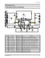
4-1 ASSY BOARD & PARTS LIST FOR SERVICE

4 Electrical Parts List

No

-

Description

ASSY PDP PANEL

ASSY PCB X MAIN

ASSY PCB Y MAIN

ASSY PCB LOGIC MAIN

ASSY PCB BUFFER(up)

ASSY PCB BUFFER(down)

ASSY PCB BUFFER(E)

ASSY PCB BUFFER(F)

ASSY PCB BUFFER(G)

ASSY PCB SMPS

ASSY PCB MISC DIGITAL

ASSY PCB MISC ANALOG

Code No

BN96-01209A

BN96-00870A

BN96-01211A

BN96-01212A

BN96-00872A

BN96-00873A

BN96-01213A

BN96-01214A

BN96-01215A

BN96-01217A

BN94-00536A

BN94-00536B

Specification

M3,S42D-YD,V3,42INCH,SEMCO SMPS,D65A,V3.1

M3,S42SD-YD,D65A,X MAIN BOARD,LJ92-00758A,V3

M3,S42SD-YD,V3,42INCH,V3.1,SDI CODE,LJ92-00944B

M3,S42SD-YD,V3,42INCH,V3.1,SDI CODE,LJ92-00975C

M3,S42SD-YD,D65A, Y BUFFER(UP) LJ92-00796A,V3

M3,S42SD-YD,D65A, Y BUFFER  LJ92-00797A,V3

M3,S42SD-YD,V3,42INCH,V3.1,SDI CODE,LJ92-00811A

M3,S42SD-YD,V3,42INCH,V3.1,SDI CODE,LJ92-00812A

M3,S42SD-YD,V3,42INCH,V3.1,SDI CODE,LJ92-00813A

SPP4231,PS42D4S,110~240V

PPM42S3Q.D61B,NEWTON 2

PPM42S3Q.D61B,NEWTON 2

Summary of Contents for PPM42S3QX/XAA

Page 1: ...DISPLAY TV Chassis D61B Model PPM42S3QX XAA PLASMA DISPLAY TV CONTENTS Specifications Alignment and Adjustments Exploded View and Parts List Electric Parts List Schematic Diagrams 1 2 3 4 5 SERVICE M...
Page 2: ...79 D x 630 5 H mm 40 43 W x 3 11 D x 24 82 H inches 31 Kg 68 34 lbs without stand 107 Cm 42 Inches AC 120V 60Hz AC100 250V 50 60Hz 330 Watts 852 H X 480 V RS 232C IN Mini jack RS 232C OUT D SUB 9P VI...

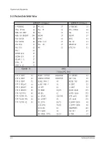
Page 3: ...and enters service mode If you fail to enter service mode repeat steps 1 and 2 above 2 1 2 Initial DISPLAY State of SERVICE MODE 2 1 2 A OSD DISPLAY 2 1 2 B Button Operations in SERVICE MODE 1 VSP943...

Page 4: ...AV 01 SECAM AV 27 NTSC AV 01 ASI II 500 DNIe Video PC DVI PI P R CONT 32 PI P G CONT 32 PI P B CONT 32 PI P R BRIGHT 00 PI P G BRIGHT 00 PI P B BRIGHT 00 PI P FILTERIC 00 PI P FILTER ML 00 PI P FILTER...

Page 5: ...LC 00 FI LTER YPASS 00 R GAMMA 32 G GAMMA 32 B GAMMA 32 H POSITION 00 V POSITION 00 H SIZE 00 V SIZE 00 OVERSCAN R 50 OVERSCAN G 50 OVERSCAN B 50 AD9888 Vi deo Comp PC CXA2101 Vi deo COMP R GAI N 71 1...

Page 6: ...VSYNC WIDTH 02 HSYNC WIDTH 12 LOG PATTERN 00 LOG HIGH LEVEL 00 LOG LOW LEVEL 00 ASI COLORBAR 00 I C W B D ata V id e o S V H S C om p on e nt P C D V I D N Ie B r igh t 4 1 5 8 4 3 3 6 C o ntr ast 5...

Page 7: ...At this time do not adjust the gain of AD9888 the Highlight W B does not need to be adjusted since its deviation falls within valid distribution range PC adjustment is same as DTV adjustment The offse...

Page 8: ...t measure point High Light measure point V id e o S V H S C o m p o n en t P C D V I T im ing 9 2 5 LTH P A L B 7 2 0 p 6 4 0 4 8 0 6 0 H z 6 4 0 4 8 0 6 0 H z H L x 2 7 5 2 8 0 2 8 0 2 8 0 y 2 8 0 2...

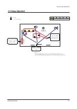
Page 9: ...S Vs VSCAN VSET VA VE VSET VSCAN VE VA VS Adjust the S MPS voltage using the VR Variable Resistor Validate the SMPS voltage Not used by this Model Common use with Other Models S MPS Fan power source C...

Page 10: ...A BN96 00872A BN96 00873A BN96 01213A BN96 01214A BN96 01215A BN96 01217A BN94 00536A BN94 00536B Specification M3 S42D YD V3 42INCH SEMCO SMPS D65A V3 1 M3 S42SD YD D65A X MAIN BOARD LJ92 00758A V3 M...

Page 11: ...HIPS V 1 T0001 BN96 00314C ASSY COVER P BACK PS42P3S AL5052 T1 2 DG 1 T0532 BN96 00676A ASSY MISC P FAN PPM42S3 2 M0764 BN96 00756A ASSY STAND P SCREW PPM50H3 SCREW PE BAG 1 T0073 BN96 00870A ASSY PD...

Page 12: ...BOTTOM ASSY 42P3S AL5052 1 S N A T0915 BN61 00141A HOLDER MODULE 42P3 AL DIECASTING 4 S N A T0918 AA60 00110H SPACER FILTER 42P3 P U FROM 960 5 6 1 S N A T0918 AA60 00110J SPACER FILTER 50P3 P U Form...

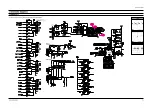
Page 13: ...nnector COMPONENT1 S Video Analog Digital Board CXA2151Q IC103 TP02 TP03 TP01 5 Schematic Diagrams Samsung Electronics Schematic Diagrams 5 1 5 1 ANALOG 1 TP01 TP02 TP03 This Document can not be used...

Page 14: ...Schematic Diagrams 5 2 Samsung Electronics R246 To DC FAN FAN PART 50 R247 TILT SENSOR 3D COMB FILTER 5 2 ANALOG 2 This Document can not be used without Samsung s authorization...

Page 15: ...hematic Diagrams 5 3 MONITOR OUT VIDEO From SMPS Board External Speaker MONITOR OUT SOUND 12V_AMP 1 2 BD701 TP06 TP07 TP05 TP04 5 3 ANALOG 3 TP04 TP05 TP06 TP07 This Document can not be used without S...

Page 16: ...5 4 ANALOG 4 Schematic Diagrams 5 4 Samsung Electronics 74HCT573 74HCT573 This Document can not be used without Samsung s authorization...

Page 17: ...Samsung Electronics Schematic Diagrams 5 5 5 5 CONTROL AA32 00013B This Document can not be used without Samsung s authorization...

Page 18: ...Schematic Diagrams 5 6 Samsung Electronics 5 6 SMPS 1 This Document can not be used without Samsung s authorization...

Page 19: ...Samsung Electronics Schematic Diagrams 5 7 5 7 SMPS 2...

Page 20: ...Schematic Diagrams 5 8 Samsung Electronics 5 8 SMPS 3...

Page 21: ...Samsung Electronics Schematic Diagrams 5 9 5 9 SMPS 4...

Page 22: ...Schematic Diagrams 5 10 Samsung Electronics 5 10 DIGITAL 1 Connector 50 63 HD Analog Digital board PC D SUB DVI SOUND 42 SD 42 HD TP08 TP10 TP09 TP08 TP09 TP10...

Page 23: ...ng Electronics 5 11 TP11 TP12 TP13 TP14 TP16 TP19 TP17 TP18 TP15 Schematic Diagrams 5 11 DIGITAL 2 TP11 TP12 TP13 TP14 TP15 TP16 TP17 TP18 TP19 This Document can not be used without Samsung s authoriz...

Page 24: ...Diagrams Samsung Electronics ANALOG EDID EPROM BNC Connector PC D SUB From SMPS board TP23 TP22 TP20 TP21 TP24 5 12 DIGITAL 3 TP20 TP21 TP22 TP23 TP24 This Document can not be used without Samsung s...

Page 25: ...ics Schematic Diagrams 5 13 USER EPROM 256K RS232C IN Flash Memory B12 1204 002105 From Remote Control board RS232C OUT TP25 TP26 5 13 DIGITAL 4 TP26 TP25 This Document can not be used without Samsung...

Page 26: ...5 14 Schematic Diagrams 5 15 TP27 TP28 5 14 DIGITAL 5 TP28 TP27 This Document can not be used without Samsung s authorization...

Page 27: ...Schematic Diagrams 5 15 5 15 LVDS Connector 5 15 DIGITAL 6 This Document can not be used without Samsung s authorization...

Page 28: ...5 16 Schematic Diagrams Samsung Electronics 5 16 DIGITAL 7 This Document can not be used without Samsung s authorization...

Page 29: ...Samsung Electronics Schematic Diagrams 5 17 DIGITAL EDID EPROM DVI Connector 5 17 DIGITAL 8 This Document can not be used without Samsung s authorization...

Reviews: