background image

UHD TV

SERVICE

Manual

UHD TV

Contents

1. Precautions

2. Product specifications

3. Disassembly and Reassembly

4. Troubleshooting

5. Wiring Diagram

Project : QRQ50O
Chassis : QWE90
Model

: QN32Q50RAF

QN32Q50RAF

Summary of Contents for QN32Q50RAF

Page 1: ...UHD TV SERVICE Manual UHD TV Contents 1 Precautions 2 Product specifications 3 Disassembly and Reassembly 4 Troubleshooting 5 Wiring Diagram Project QRQ50O Chassis QWE90 Model QN32Q50RAF QN32Q50RAF ...

Page 2: ... 2 8 2 4 3 Shortcuts 2 11 2 4 4 Bixby 2 13 2 5 The Samsung Smart Remote 2 16 2 6 Using the TV Controller 2 18 3 Disassembly and Reassemble 3 1 3 1 TV Disassembly 3 1 4 Troubleshooting 4 1 4 1 Function Control Operation Test 4 1 4 2 Power 4 2 4 2 1 SMPS Standby 4 2 4 2 2 SMPS Power On 4 3 4 2 3 SMPS PANEL BACKLIGHT Parallel Wired SMPS Panel Connections 4 4 4 3 Video 4 5 4 3 1 Customer Picture Test ...

Page 3: ...9 4 11 2 Service Adjustment 4 39 4 11 3 Adjustment 4 41 4 12 LED Indicator Test 4 42 4 12 1 Diagnostic Methods Flashing Symptom Codes 4 42 4 13 Updating the TV s Software 4 43 5 Wiring Diagram 5 1 5 1 Wiring Diagram 5 1 5 2 Connector 5 3 5 2 1 Main Board 5 3 5 2 2 SMPS Board 5 7 ...

Page 4: ...Manual is a property of Samsung Electronics Co Ltd Any unauthorized use of Manual can be punished underapplicable International and ordomestic law 2019 Samsung Electronics Co Ltd All rights reserved Printed in Korea ...

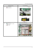
Page 5: ...ruments to pry apart the cabinet Recommend Torque 22 0 26 5lbf A strength of Torque can be changed depending on the situation 3 1 TV Disassembly Description Screws Picture Description 1 Carefully position the TV so that the screen is facing downwards Make sure to place the TV upon a soft cushion or any material that will prevent damage to the screen 2 Remove the screws connecting the stand to the ...

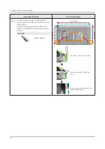
Page 6: ...l clips as indicated in red on sides and top Gently lift up the Rear Cover starting at the top being careful of function assembly at the bottom Open Jigs BN81 12884A Put the jig in the arrow position Rotate the jig and lift the Rear Cover Move the jig in the direction of the arrow to decompose Jig Direction Jig Direction Jig Direction ...

Page 7: ...g Back cover as it is 32 Bottom 4 point Locking Top 6 point Locking L 2 point Locking R 3 point Locking Center 1 Point Locking Lift top side then pull back to remove the back cover 4 Remove the Electric tapes shown on the images EMI Filament Tape Dressing Filament Tape Dressing NOTE When assembling the TV the electric tapes must be applied on the same locations Please remember to take a picture of...

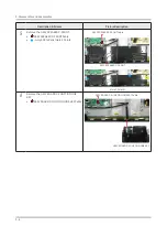
Page 8: ...ASSY SPEAKER P FRONT ASSY SPEAKER P FRONT Cable Assy SPK to Panel Hole 4 Points ASSY SPEAKER P FRONT Cable ASSY SPEAKER P FRONT Hole 3 Points 6 Remove the ASSY BOARD P FUNCTION ONE KEY ASSY BOARD P FUNCTION ONE KEY Cable ASSY BOARD P FUNCTION ONE KEY Cable ASSY BOARD P FUNCTION ONE KEY ...

Page 9: ...Reassemble Description Screws Picture Description 7 Remove the NETWORK NETWORK Cable NETWORK Cable NETWORK Disassemble WiFI 8 Remove the Cables LEAD CONNECTOR POWER SMPS MAIN FFC Cables LEAD CONNECTOR POWER Cables FFC Cables ...

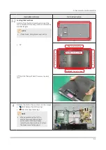
Page 10: ...Top Right corner to release the lock Use both hands to hold the board and slide to the left to release the board NOTE When installing the ASSY PCB MAIN BOARD verify the board is properly positioned in all 4 mounting slots Locking Fixing Hole Locking Slide to the left to release the board Bottom chassis Guide Fixing Hole ...

Page 11: ...charging After discharging LED ON LED OFF Measurement point 2 Remove the SMPS Board pushing to the arrow direction 1 Pushing ConnectorA 2 Insert the OPEN JIG like a picture 3 Gently lift up Top Left corner to release the lock 3 Gently lift up Top Left corner to release the lock and Slide Board to the Right Locking Fixing Hole A S DISCHARGE JIG BN81 16292A Measurement point Slide to the right to re...

Page 12: ...3 8 3 Disassembly and Reassemble Description Screws Picture Description 11 Completed the disassembly NOTE Reassembly procedures are in the reverse order of disassembly procedures ...

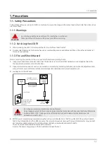
Page 13: ...l knobs insulating materials cabinet backs adjustment and compartment covers orshields isolation resistorcapacitornetworks mechanical insulators etc 3 Leakage Current Hot Check DEVICE UNDER TEST READING SHOULD NOT BE ABOVE 0 5mA LEAKAGE CURRENT TESTER TESTALL EXPOSED METAL SURFACES 2 WIRE CORD ALSO TESTWITH PLUG REVERSED USING AC ADAPTER PLUG AS REQUIRED EARTH GROUND WARNING Do not use an isolatio...

Page 14: ...ed by replacing them with components rated for higher voltage wattage etc Parts that have special safety characteristics are identified by on schematics and parts lists A substitute replacement that does not have the same safety characteristics as the recommended replacement part might create shock fire and or other hazards Product safety is under review continuously and new instructions are issue...

Page 15: ...s used The internal wiring is sometimes clamped to prevent contact with thermally hot components Reinstall all such elements to theiroriginal position 3 Afterservicing always check that the screws components and wiring have been correctly reinstalled Make sure that the area around the serviced part has not been damaged 4 Check the insulation between the blades of the AC plug and accessible conduct...

Page 16: ...harges sufficient to damage ESDs 4 Use only a grounded tip soldering iron to solderordesolderESDs 5 Use only an anti static solderremoval device Some solderremoval devices not classified as anti static can generate electrical charges sufficient to damage ESDs 6 Do not remove a replacement ESD from its protective package until you are ready to install it Most replacement ESDs are packaged with lead...

Page 17: ...antenna farawayfrom any high voltage cables and install it firmly Contact with the highvoltage cable orthe antenna falling overmay cause fire orelectric shock 7 When installing the product leave enough space 0 4m between the product and the wall forventilation purposes A rise in temperature within the product may cause fire 8 If an equipment is provided with a replaceable battery and if replacemen...

Page 18: ...RAF Front View W W Width H High D Depth H D Color Front CHARCOAL BLACK Stand CHARCOAL BLACK Dimensions W x H x D 32 Body 28 5 x16 8 x1 2 inches 723 3 x 425 6 x 29 9 mm With Stand 28 5 x18 8 x 6 1 inches 723 3 x 477 7 x154 2 mm Weight 32 Without Stand 11 7 lbs 5 3 kg With Stand 11 9 lbs 5 4 kg ...

Page 19: ...essor Motion Rate 120 HDR High Dynamic Range HDR HDR10 Yes Contrast Mega Contrast HLG Hybrid Log Gamma Yes Color ColorVolume100 by Quantum Dot Viewing Angle N A Micro Dimming UHD Dimming Local Dimming N A Auto Depth Enhancer N A Contrast Enhancer Yes Auto Motion Plus Yes Film Mode Yes Natural Mode Support Yes Audio Dolby Digital Plus Yes Dialog Enhancement Yes Sound Output RMS 20W Speaker Type 2CH...

Page 20: ... Bluetooth Low Energy Yes WiFi Direct Yes TV Sound to Mobile Yes Sound Mirroring Yes Tuner Broadcasting Digital Broadcasting ATSC ClearQAM Analog Tuner Yes Connectivity HDMI 3 USB 2 Component In Y Pb Pr 1 Composite In AV 1 Common Use for Component Y Ethernet LAN Yes Audio Out Mini Jack N A Digital Audio Out Optical 1 RF In Terrestrial Cable input Satellite input 1 1 Common Use for Terrestrial 0 Ex...

Page 21: ...rs Grayscale Caption Moving Learn Menu Screen US English Video Zoom Key Repeat Delay Digital Clean View Yes Auto Channel Search Yes Auto Power Off Yes Caption Subtitle Yes Connect Share HDD Yes ConnectShare USB 2 0 Yes EPG Yes Extended PVR N A Game Mode Yes Auto Game Mode Freesync N A IP Control Yes OSD Language English Spanish French BT HID Built in Yes USB HID Support Yes V Chip Yes IPv6 Support...

Page 22: ...can be purchased separately The part code for some accessories may differ depending on your region The provided accessories mayvary depending on the model Product Code No Product Code No Samsung Smart Remote BN59 01312G TV Power Cable 3903 001117 Batteries AA x 2 4301 000101 Warranty Card BN68 00514K User Manual BN68 09856A Regulatory Guide BN68 09371A ...

Page 23: ...s on a registered device For more information refer to Displaying the Home Screen 2 Settings When the focus is moved to Settings a list of quick settings icons appears above the top of the menu You can quickly set frequently used functions by clicking the icons 3 Source You can select an external device connected to the TV For more information refer to Switching between external dev ices connected...

Page 24: ...t Remote there may be restrictions to entering Ambient Mode Because this function is a QLED TV specific function it may not be supported depending on the model For more information about the Ambient Mode refer to Using the Ambient Mode 7 Universal Guide Universal Guide is an app that allows you to search for and enjoyvarious content such as TV shows dramas and movies in one place Universal Guide c...

Page 25: ...ictions to entering Ambient Mode Ambient Mode browserscreen The image on your TV may differfrom the image above depending on the model and geographical area When you press the or button in Ambient Mode the Ambient Mode browser screen appears at the bottom of the screen In the Ambient Mode browser screen you can select content and change the Ambient Mode settings 1 Function and content preview When...

Page 26: ...is function may not be supported depending on the geographical area Photo Allows you to set a photo stored in your mobile device or Samsung Cloud as the wallpaper of the Ambient Mode screen To import photos from your mobile device or Samsung Cloud use the SmartThings app on your mobile device Trend The TV provides pictures and stories related to a specific topic or interest you select This functio...

Page 27: ...ot be supported depending on the content Brightness Adjusts the brightness of the content Saturation Adjusts the saturation of the content ColorTone Adjusts the colors of the content Red Tone Green Tone Blue Tone Adjusts the red green blue contrast View detailed information about the content When you are enjoying content in Ambient Mode press the up directional button to view detailed information ...

Page 28: ...es You can select an external device connected to the TV 2 Channels Press the button to add a broadcast channel You can move or remove added broadcast channels 3 e Manual Displays the e Manual guide 4 Settings Displays the main on screen menu 5 Terrestrial Cable Satellite orService Provider Choose the broadcast type of the content Terrestrial Cable Satellite or Service Provider This function may n...

Page 29: ...2 12 2 Product specifications Removing a channels 1 Move the focus to the channels to remove 2 Press the down directional button 3 Select Remove The selected channel is removed ...

Page 30: ...i Bixby and the Bixby icon at the bottom of the TV screen is activated in Listen mode and a beep sounds Speak what you want If Bixby does not respond to yourvoice turn on the Voice Wake up function and then try again Explore Now Settings Voice Wake up Talking with Bixby using buttons You can also make a conversation with Bixby using the Samsung Smart Remote buttons Press and hold the button on you...

Page 31: ...esponse You can change Bixby s voice This function may not be supported depending on the selected Bixby s language Voice Wake up When you turn on the function Bixbywill respond to yourvoice This function may not be supported depending on the model or geographical area Sound feedback You can set Bixby to tell you verballywhen it starts hearing yourvoice Privacy You can set whether to allow Bixby to...

Page 32: ...ide complete results You may be required to pay for some apps Consequently you may encounter a service application or contract To change the current channel by saying channel names as voice commands you must finish Set Up YourService Provider If Set Up YourService Provider is not completed you can complete it using Reset Settings General Reset To use the voice text input function and the search fu...

Page 33: ...evious menu When pressed for1 second ormore the running function is terminated When pressedwhileyou arewatching a program the previous channel appears Play pause When pressed the playback controls appearwhile the media content is playing Smart Hub Returns to the Home Screen VOL Volume Move the button up ordown to adjust thevolume To mute the sound press the button When pressed for 1 second ormore ...

Page 34: ...nglish When you turn on the TV for the first time the Samsung Smart Remote pairs to the TV automatically If the Samsung Smart Remote does not pair to the TV automatically point it at the remote control sensor of the TV and then press and hold the buttons labeled and as shown in the figure on the left simultaneously for 3 seconds or more Installing batteries into the Samsung Smart Remote Pairingthe...

Page 35: ...vailable formobile devices runningAndroid 6 0 orhigheroriOS10 orhigher Noise mayoccurtemporarilywhen the TVcommunicateswith mobile devices Usingthe TVController You can turn on the TVwith the TVController button at the bottom of the TV and then use the Control menu The Control menu appearswhen the TVController button is pressedwhile the TVis On Formore information about its usage referto the figur...

Page 36: ...F 9 9 LED 1 7Vdc pin 8 and VCC for3 3Vdc pin 3 If missing suspect Function Assy Cable Main board 4 If LED is ON 9 9 Switch Operation activates on screen display On Screen Selections with Function Control If missing 9 9 Key_Input1 pin 6 change to 0Vwith a command If wrong voltage or no change 9 9 Switch forstuck ormiss operation 5 Check IR operation with Standard Remote command changes 6 Check SDA ...

Page 37: ... 1 TV in Standby 9 9 Check StandbyLED Indicator 2 If Not Lit 9 9 Check AC120Vac Line 3 If missing 9 9 Check AC120Vac Source PowerCord 4 If OK 9 9 Check resistance on SMPS FUSE afterfirst removing AC powercord 5 If fuss are open replace SMPS 6 If fus are OK 9 9 Standby A13V Always On to Main Board 7 If any missing remove the SMPS connectorto the Main Board 9 9 Check Standby A13V again If OK replace...

Page 38: ... plugged into AC Power 2 If voltage errororno change 9 9 Jog Function Control Test 3 If OK replace Main Board 9 9 All A13V supplies forapprox 12 7VDC pins 3 5 7 9 4 If anywrong voltages remove SMPS connectorto Main Board 9 9 All A13V again for 12 7VDC pins 3 5 7 9 5 If OK replace Main Board 6 If still wrong voltage replace SMPS 9 9 OD_ON OFF OverVoltage Detect pin 4 3 3Vdc Operating Normal 7 If 0V...

Page 39: ...9 9 The Supply Drive pins and pins All should measure same If a Minus pin measures low near 0 volts a string s of LEDs are likely open 9 9 Replace Panel If a pin measures lowvoltage 9 9 Defective SMPS BACKLIGHTDIMMING PROBLEMS Go to Menu Picture Backlight and vary level 0 50 If no backlight changes observed 9 9 Panel Connector CNL801 minus pin voltages and PWM_BLU control voltages CNM801 while cha...

Page 40: ...ck yourexternal devices and connections Try picture reset by selecting Menu Picture Reset Picture Update to the latest software version by selecting Menu Support Software Update Check Signal Source and other inputs Fail Pass Pass Picture Test Test1 Test 2 Test 3 Fail Pass Replace Main T CON Board Fail Fail Pass Picture Test Test1 Test 2 Test 3 Fail Fail Pass Replace Main T CON Board Fail Fail Fail...

Page 41: ...s ENTER Factory mode SVC Test Pattern Main Board Muse L T CON 1 ScalerPattern US Post Pattern 2 SoC TCON Test Pattern Factory Mode 1 Verify ScalerPattern and US Post Pattern 2 Verify SoC TCON Test Pattern 4 6 4 Troubleshooting ...

Page 42: ...st1 Mute 1 4 7 Mute Video Operation Generated on Main Section If OK 9 9 Source Input Cables 9 9 Otherinputs If Noisy 9 9 Pre FRC Section Test Patterns PRE FRC Section CustomerPicture Test 2 Video Operation Generated at Pre FRC Section If OK 9 9 Replace Main T Con Board If Noisy 9 9 Post FRC Section 4 7 4 Troubleshooting ...

Page 43: ... OK 9 9 Replace Main T Con Board If Noisy 9 9 Mute 3 6 9 Mute T CON Section Mute 3 6 9 Mute May not be available for Larger models over 70 inches Video Operation Generated at T CON Section 1 If OK 9 9 Replace Main T CON Board 2 If Noisy 9 9 Main T CON Board 9 9 Panel 4 8 4 Troubleshooting ...

Page 44: ... CON Pattern in Factory Mode Use type of Noise observed Bars single lines video distortion etc to help If noise is only on one half of screen check swap panel cables Verify Defective Panel Cables TV Main T CON Board or Panel 4 9 4 Troubleshooting ...

Page 45: ...ptical Digital Out Errors 9 9 Red light from Optical Digital Out If missing replace Main Board Main Board No HDMI Audio 9 9 Source HDMI Cable Swap with other HDMI Inputs Sources Perform EDID Write in Factory Mode Can restore missing HDMI Audio 9 9 Bulletins and Latest firmware on TV If not restored replace Main Board Check Audio Format PCM Dolby based on external Receiver ARC Issues 9 9 HDMI Cable...

Page 46: ...typasscode 9 9 Check Wi Fi signal strength at TV use WiFi AnalyzerorsimilarApp Try another source Hot spot or Test Router 9 9 Check related Bulletins 9 9 Check FactoryMode SVC Info WiFi ErrorCount replace module forhigh errorcounts Routerto Network Failure 9 9 Check Network Status Check Network Status TV Router Internet Instruct the customer the TV has proper connection to the router and is likely...

Page 47: ...still fails 9 9 DNS Test with setting to Auto Mode If it fails both Manual Auto problem is ISP orRouter ISP Blocking If it Fails 9 9 Internet Service Provideris Active 9 9 With DNS setting at 8888 9 9 With Hot Spot Samsung ServerTest If it Fails 9 9 Network Status If OK 9 9 Reset Smart Hub 9 9 Terms of Agreement are accepted Samsung Apps If it Fails 9 9 Reset Smart Hub 9 9 Samsung Apps load correc...

Page 48: ...the TV s Main Board If ESN number is missing NF do not replace the Main Board Reset TV Clock and check for correct Time Date Netflix relies on correct settings Reset Smart Hub Reset Apps In Factory Mode ForStreaming Issues Go to TVWeb Browser Go to speedof me testmy net 9 9 Check Speed forat least 5 Mbps HD streaming 25 Mbps 4K Streaming 9 9 Check Latencyforless than 50ms 4 13 4 Troubleshooting ...

Page 49: ...dule PIN Pin1 Pin10 Pin Assignments Pins Pin Name VOLTAGE V 1 BT_WAKE_UP 3 3 2 UART_TX 3 3 3 WIFI_USB_SUSPEND 3 3 4 GND GND 5 USB DP USB 6 USB DM USB 7 GND GND 8 VCC 5 9 WIFI_WAKE_UP 3 3 10 Reset 3 3 4 14 4 Troubleshooting ...

Page 50: ...set returns TV to out of box condition Must perform when replacing Main Board or Full One Connect Factory Reset Select Factory Reset Factory Reset Type 32A6AU0QR Writing Type Local Set US SW Model QRQ50S Model Code QN32Q50RAFXZA TUNER Ch Table NONE MRTOption Production Option EngineerOption SVC Info ER Count Important to check for errors Resets to 0 with Factory Reset 9 9 Check before resetting TV...

Page 51: ...MI Option 32A6AU0QR US QN32Q50RAFXZA NONE DTCP Not Supported X FRC MUSE L xxx 60Hz HW 0x0F DIMMING GLOBAL FF LD FW1 LD FW2 TCON MUSE L FW xxxx DATA xxxx Model QN32Q50RAFXZA Wired MAC SUCCESS Wireless MAC SUCCESS WIFI Version x x xx xxx xxx xxxxxx CO NfO W MO D HX PO AO O S N RO FP SIO WS DIO UX IO T NS 1100 Factory Data Ver XXX Fixed Ver XX EERC Version XX WB Ver 1 CPLD LD N A SmartControl Board I...

Page 52: ... 2 Verify SoC TCON Test Pattern ScalerPattern OFF US Post Pattern OFF FRC Pre Pattern 0 FRC Post Pattern 0 SOC TCON Pattern 0 SOC TCON Pattern Level 255 FRC OSD Pre Pattern 0 FRC OSD Post Pattern 0 FRC2 Pre Pattern 0 FRC2 Post Pattern 0 SOC TCON2 Pattern 0 SOC TCON2 Pattern Level 255 SOC TCON3 Pattern 0 SOC TCON3 Pattern Level 255 4 17 4 Troubleshooting ...

Page 53: ...T 2 BTNO DETECTION COUNT 0 BTDETACHMENTCOUNT 1 BTMGTOPEN FAIL COUNT 0 BTMGTDISCONNECTCOUNT 0 BTTVAUDIO DROP 0 BTAUDIO TIMER EXP 0 Camara ER Count FRC3D Emergency Reboot On off ON FRC3D ER Count 0 Fan ErrorCount 0 WD Count Watch Dog Hardware related issue AR Count Auto Reset software i e Apps related 9 9 important ErrorCount Status Screen Verify each item listed 4 18 4 Troubleshooting ...

Page 54: ...n Control Debug SVC ADC WB Advanced EDID Sub Option 3 Select EDID OFF to ON RightArrow Key EDID ON OFF ON 4 Select EDID WRITE ALL EnterKey EDID WRITE ALL Success 5 Wait to Success RightArrow Key EDID WRITE ALL Wait 6 Confirm EDID WRITE ALL Success Menu Key EDID WRITE ALL Success 4 19 4 Troubleshooting ...

Page 55: ...ing Type Success appears in the Option Table If the model Type you entered doesn t exist it will not load If you entered over 10 digits an Information screen box is full appears Factory Reset Type 32A6AU0QR Writing Type Success Local Set US SW Model QRQ50S Model Code QN32Q50RAFXZA Writing Type Success Writing Type digits exceeded 32A6AU0QR 7 Complete rest of Option Byte Table info 8 Press soft pow...

Page 56: ...4 Enter exact Model Type using cursors Set Model Code UN55RU7400UXCE 5 If you entered over19 digits an Information screen box is full appears IMPORTANT It will accept wrong model code be sure to entercorrect code Factory Reset Type 32A6AU0QR Writing Type Success Local Set US SW Model QRQ50S Model Code N32Q50RAFXZA1 Model Code digits exceeded Wrong Model Code Entry N32Q50RAFXZA1 6 Complete rest of ...

Page 57: ... keys in this sequence With ConsumerRemote IR Remote 9 9 Remote Button NTSC POWER OFF MUTE 1 8 2 POWER ON PAL POWER OFF INFO MENU MUTE POWER ON With Factory Remote INFO FACTORY 2 The following screen appears Please refer to Detail Factory Option page for details Detail Factory Option 4 22 4 Troubleshooting ...

Page 58: ...MAIN Information Multi Bom Panel Info Panel Type Description SMPS Assy Chassis Assy PCB Main S W Model FA01 BN95 06039A 32A6AU0QR PRODUCT LCD SDC BN44 01017A BN91 21518N BN94 14966A QRQ50 MAIN Factory Option Local Set US Bom Model 50RA Front Color Q F RQ50 B 32 PBA Factory Option Panel Type 00GD00020 Local Set US S W Model QRQ50 Bom Model Follow S W Model 4 23 4 Troubleshooting ...

Page 59: ...enu Name Data Range EDID EDID ON OFF OFF EDID WRITE ALL EDID WRITE HDMI EDID WRITE PC HDMI EDID Ver HDMI EDID Port Sub Option RS 232 Jack UART EXT Link Support ON Serial Log On Off OFF Watchdog ON FRC Monitoring OFF Checksum 0x0000 Fast Boot In Production ON USB Serial OFF ECO IC TYPE NOT_DETECT COLOR IC TYPE RISG315 Info Link Server Type development Info Link Country None TTX Group UserOSD 4 24 4...

Page 60: ...M_MC ON UNIQUE TRIPLET ON FS_FAV OFF Private Range USE ON SCSA Support OFF OCM Reboot ON SPI Protection FKP Server Type Default OCM Support ON Preloading Support ON Multitasking Support ON Browser preloading Support FULL EXT IR Boot Support OFF APP BOOTING SUPPORT ON NagSam Support OFF EWBS Support OFF MVPD MBR Provider COMCAST cloudscan Always Upload OFF FirstScreen Cach Size 300 Hotel Option Hos...

Page 61: ...se comes from weakness electromagnetic field TVwill be set Mute automatically Only default on in North America Pilot Level High Thld 0x20h The High threshold value of stereo signal If Pilot level is greather than High threshold value recognize Stereo signal Pilot Level Low THLD 0x10h The Low threshold value of stereo signal If Pilot level is less than Low threshold value recognize Mono signal Carr...

Page 62: ...hecksum 0x4972 Lipsync USB Test Ready Lipsync BT Checksum 0x0000 TPvolume 0xc4h TP Scale 0x6ch TP EQ CheckSum NONE Debug Factory Menu Name Data Range Spread Spectrum LVDS Spread 0 DDR Spread 0 Period 0 Amplitude 0 HD DDR SSC ON OFF OFF HD DDR SSC Value 0 FHD DDR SSC ON OFF OFF FHD DDR SSC Value 4 UHD DDR SSC ON OFF ON UHD DDR SSC Value 0 P eBus SSC ON OFF OFF P eBus Value 0 LVDS SSC ON OFF OFF LVD...

Page 63: ... 1 ADV7619 H_V_DE strength 1 AP DDR SSC ON OFF OFF AP DDR SSC Value 0 AP USIT SSC ON OFF ON AP USIT SSC Value 13 OCM Vx1 SSC ON OFF OFF OCM Vx1 SSC Value 0 TCON USIT SSC ON OFF BYPASS DDR Margin A CTRL_OFFSET_0_3 0 A CTRL_OFFSET_D 0 B CTRL_OFFSET_0_3 0 B CTRL_OFFSET_D 0 BT_ON_OFF ON RF Mute Time 600ms TunerMargin 3 European specifications FRC FRC FDISPLAY ON OFF OFF 3D FDISPLAY ON OFF OFF PC Mode ...

Page 64: ...nel S N1 Panel S N 2 Panel S N 3 Panel S N 4 MPEG Margin H 264 Margin CAM Wait Time Voice Debug PowerManagement Cert Option RM_BIST_DTV RM_BIST_ATV RM_BIST_CABLE SerDES Check SerDES Tuner HDMI SW Failure HDMI Rx Failure MP Failure Main SerDES Failure Jack SerDES Failure Stress Mode Log Analyzer ErrorPopup On Off DeadLock KILL CES Option CES Convergence Option 4 29 4 Troubleshooting ...

Page 65: ...UPPORT 0 DB Download MRT Option Dump Failure Picture Data Dump Failure VCONF Dump Failure Read Eco SensorData No Signal PowerOFF Alert Option Default HDMI1 Booting SVC Factory Menu Name Data Range Self Test forHW the Output of test pattern from each IC Info Reset Apps Reset SVC Reset SPI Flash Reset Data Sync Reset Factory Data Reset OPTION_HDMI DVI HDMI SOUND Auto HDMI HOT PLUG Disable HOTPLUG SW...

Page 66: ...0 HDMI 3D DET 1 HOT PLUG OFF HOLD TIME 600ms HDMI MUTE TIME 0ms HDMI NFST UNMUTE TIME 800ms HDMI FST UNMUTE TIME 0ms REPEA AUDIO PKT OFF HDMI Stable Count 3 HDMI HDCP EN OFF HDMI HDCP EN FLAG 85 POWER ON FLT CNT LOS HDCP UPDATE SPI READY SPI VERSION 0 HdmiRx EQ 0 HDMI TMDS ERR DET 1 DVB CI TS Clock delay TC 0 TS Clock delay S 0 CI Control Buf ON ON TS Clock delay CPU 1 TS Clock delay TC2 0 TS Cloc...

Page 67: ... FW UPGRADE T CON CheckSum T CON2 Usb Download T CON2 CheckSum PANEL EEPROM UPGRADE PANEL FLASH UPGRADE Logic Usb D L SUBMICOM UPGRADE Upgrade Sub Micom Program SUBMICOM JP USB UPGRADE BT UPGRADE BT FREEPAIRING Function Upgrade FRC3D FW UPGRADE FRC3D SRP UPGRADE FRC3D LD UPGRADE FRC2 3D FW UPGRADE Camera Upgade Upgarde Camera module There is upgrade program in Main Image Mic Upgrade Upgarde MIC in...

Page 68: ... Data Backup CAL Data Restore MICOM POWER OFF ON NTV CU FWVER 0 ATV IF AGC SPEED 0 Upgrade UHD OSD Test 0 Main USB Path JackP USB Path Source Direct On Off OFF Apps Update Auto Power LAST POWER SMCE Control Motor Test Cube Test V APP OFF Picture Direct On Off OFF SVC Panel ORIGINAL S N Serial number Writing S N ADC WB Factory Menu Name Data Range ADC AV Calibaration Comp Calibration 4 33 4 Trouble...

Page 69: ...G_L 128 2nd_B_L 128 2nd_R_H 69 2nd_G_H 69 2nd_B_H 69 White Balance R Offset 128 G Offset 128 B Offset 128 R Gain 128 G Gain 128 B Gain 128 WB W2_R_Offset 128 WB_W2_B_Offset 128 WB_W2_R_Gain 136 WB_W2_B_Gain 76 WB_N_R_Offset 128 WB_N_B_Offset 128 WB_N_R_Gain 131 WB_N_B_Gain 119 MGA MGA On Off OFF R1_Gain G1_Gain B1_Gain R2_Gain G2_Gain 4 34 4 Troubleshooting ...

Page 70: ...6_Gain G6_Gain B6_Gain R7_Gain G7_Gain B7_Gain R8_Gain G8_Gain B8_Gain R9_Gain G9_Gain B9_Gain R10_Gain G10_Gain B10_Gain SPI White Balance SPI White Balance On Off SPI R Offset SPI G Offset SPI B Offset SPI R Gain SPI G Gain SPI B Gain SPI N Rgain SPI N Bgain SPI N Roffset SPI N Boffset 4 35 4 Troubleshooting ...

Page 71: ...Factory Menu Name Data Range SPI W2 Rgain SPI W2 Bgain SPI W2 Roffset SPI W2 Boffset SPI MGA WB Data to SPI Advanced 4 36 4 Troubleshooting ...

Page 72: ...l located in the back chassis of panel and choose same Type code from the list Home Updates Exit 55A1QU7QN 55L1QU7QN 75L1QU7QN 55A1QU8XN 55L1QU7QN 55A1QU7QN 65D6AU0NN 65A1QU7QN 65L1QU7QN 65A1QU8XN 65L1QU8XN 55A6AU0NN 55L6AU0NN 32A6AU0QR Type list in the Factory Menu Type in Panel Label CY XX 2019 01 XX 32A6AU0QR XX 2019 XX XX 32A6AU0QR Factory Reset Type 32A6AU0QR Writing Type Local Set US SW Mode...

Page 73: ...X QRQ50 QNQ6FK BEN QRQ80 QRQ70 QRQ50S QRQ75 QRQ80_OC QRQ75 URU710D URU730D URU7100 UNU7500 QRQ50 SW Model list in the Factory Menu SW Model in Label Rating Model code Check14 digits of Model code and type in e g Model Code QN32Q50RAFXZA QN32Q50RAFXZA Model code in Label Rating Home Updates Exit Factory Reset Type 32A6AU0QR Writing Type Local Set US SW Model QRQ50 Model Code QN32Q50RAFXZA TUNER Ch ...

Page 74: ...n Adjust Specification Source Setting Mode Pattern Use Equipment HDMI 1280 x 720 60 Hz Pattern 24 Chess Pattern CA210 Master MSPG925 Generator Chess Pattern Use other equipment only after comparing the result with that of the Master equipment Input mode Calibration Pattern CVBS IN Model_ 1 Perform in NTSC B W Pattern 24 Lattice Component IN Model_ 6 Perform in 720p B W Pattern 24 Lattice PC Analog...

Page 75: ...gh level menu 8 You can see the change of the Comp Calibration status from Failure to Success Method of ColorCalibration PC 1 Apply the VESA XGA Lattice N0 21 pattern signal to the PC IN port 2 Press the Source key to switch to PC mode 3 EnterService mode 4 Select the ADC menu 5 Select the PC Calibration menu 6 In PC Calibration Off status press the key to perform Calibration 7 When Calibration is...

Page 76: ...tory Mode 2 Select ADC WB menu 3 Select White Balance menu Option Control Debug SVC ADC WB Advanced White Balance Low Light Sub Brightness R offset G offset B offset Hight Light Sub Contrast R gain G gain B gain 4 41 4 Troubleshooting ...

Page 77: ... 10min 4 sec 30sec Cold Boot 20 30sec x 5 time x 5 time x 5 time x 5 time x 5 time 4 se 4 se 4 se 4 se Blinks1 time when cold boot Main Board WDC Reboot Flash Error Flash 1 time Panel Error Reboot Flash Error Flash after 10cm 2 time SMPS Error Reboot Flash Error Flash 3 time Bluetooth WIFI Cold Boot 30 sec after module starts 4 time AOC Cold Boot 30 sec after module starts Signal level below thres...

Page 78: ...the USB device to the TV to update To update using a USB device download the update package from Samsung com to your computer Then save the update package in the USB device s top level folder Otherwise the TVwill not be able to locate the update package Updating the TV automatically Settings Support Software Update Auto Update If the TV is connected to the Internet you can have the TV update its s...

Page 79: ...5 1 5 Wiring Diagram 5 Wiring Diagram 5 1 Wiring Diagram SMPS CNM801 MAIN CN202 CN1301_UT CN1300 Speaker Func on CNL801 WIFI BT CN1403_NMOB CN1601 ACN01 ...

Page 80: ... 4 5 3 2 Part Name Connection Part Spec Code No 1 LEAD CONNECTOR POWER SMPS MAIN 12P 250 32 BN39 02217C 2 FFC CABLE Main Source B 96P L400 32 BN96 39891D 3 FFC CABLE Main Source B 96P L250 32 BN96 44601B 4 LEAD CONNECTOR SUB ASSY Main FUNCTION 12P L350 32 BN39 02457C 5 LEAD CONNECTOR SUB ASSY Main WiFi 10P L200 32 BN39 02465B ...

Page 81: ... HDMI2 6 CN2001 HDMI1 8 CN1502_LAN LAN 7 CN1901 COMPONENT AV 9 CN1601 IR FUNCTION ACN01 Speaker 0 CN1403_NMOB BT WIFI CN202 POWER CN1301_UT USI T RIGHT CN1300 USI T LEFT Main Board Pin Map 1 CN1903 OPTICAL 1 SPDIF_OUT 2 B5V_PW 3 GND 2 CN1402 USB1 1 USB1_VCC_5V_PW 2 D 3 D 4 GND 3 CN1401 USB2 1 USB2_VCC_5V_PW 2 D 3 D 4 GND ...

Page 82: ...D 9 HDMI3_RX0 _HDMI 10 HDMI3_RX_CLK _IN_ HDMI 11 GND 12 HDMI3_RX_CLK _IN_ HDMI 13 CEC 14 GND 15 HDMI3_SCL_DDC 16 HDMI3_SDA_DDC 17 HDMI3_INS_DET 18 HDMI3_5V_PW 19 HDMI3_HPD 7 CN1901 COMPONENT AV 1 GND 2 COMP_Y AV_IN_CVBS 3 IDENT_AV 4 GND 5 COM_PB 6 IDENT_COMP 7 GND 8 COM_PR 9 TEST_PR 10 GND 11 COMP_AV_SL_IN 12 TEST_SL 13 GND 14 COMP_AV_SR_IN 15 TEST_SR 8 CN1502_LAN LAN 1 EPHY_TXP_LAN 2 A1 8V_PW 3 E...

Page 83: ...T 39 TX_CH1_A _USIT 40 GND 41 TX_CH1_B _USIT 42 TX_CH1_B _USIT 43 GND 44 TX_CH2_A _USIT 45 TX_CH2_A _USIT 46 GND 47 TX_CH2_B _USIT 48 TX_CH2_B _USIT 49 GND 50 TX_CH3_A _USIT 51 TX_CH3_A _USIT 52 GND 53 TX_CH3_B _USIT 54 TX_CH3_B _USIT 55 GND 56 TX_CH4_A _USIT 57 TX_CH4_A _USIT 58 GND 59 TX_CH4_B _USIT 60 TX_CH4_B _USIT 61 GND 62 TX_CH5_A _USIT 63 TX_CH5_A _USIT 64 GND 65 TX_CH5_B _USIT 66 TX_CH5_B...

Page 84: ...IT 42 TX_CH11_A _USIT 43 GND 44 TX_CH11_B _USIT 45 TX_CH11_B _USIT 46 GND 47 TX_CH12_A _USIT 48 TX_CH12_A _USIT 49 GND 50 TX_CH12_B _USIT 51 TX_CH12_B _USIT 52 GND 53 TX_CH13_A _USIT 54 TX_CH13_A _USIT 55 GND 56 TX_CH13_B _USIT 57 TX_CH13_B _USIT 58 GND 59 TX_CH14_A _USIT 60 TX_CH14_A _USIT 61 GND 62 TX_CH14_B _USIT 63 TX_CH14_B _USIT 64 GND 65 TX_CH15_A _USIT 66 TX_CH15_A _USIT 67 GND 68 TX_CH15_...

Page 85: ...g Diagram 5 2 2 SMPS Board To Main Board 1 CNM801 2 CNL801 SMPS Board Pin Map 1 CNM801 1 GND 2 ANA_DIM 3 A13V 4 OD ON OFF 5 A13V 6 BLU_PWM 7 A13V 8 Power_On Off 9 A13V 10 GND 11 GND 12 GND 2 CNL801 1 1 2 1 3 2 4 2 ...

Reviews: