


BOTTOM MOUNT FREEZER
BASIC : RF265AA, RF266AA
MODEL NAME : RF265AARS
RF266AARS
RF26NBRS1
RF265AABP
RF266AABP
RF26NBBP1
RF265AAWP
RF266AAWP
RF26NBSH1
RF265AASH
RF266AASH
MODEL CODE : RF265AARS/XAA
RF266AARS/XAA
RF26NBRS1/SML
RF265AABP/XAA
RF266AABP/XAA
RF26NBBP1/SML
RF265AAWP/XAA
RF266AAWP/XAA
RF26NBSH1/SML
RF265AASH/XAA
RF266AASH/XAA
RF26NBRS1/XSA
REFRIGERATOR
REFRIGERATOR
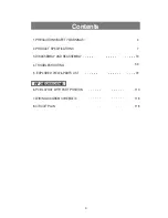
CONTENTS
For the latest parts information, Please access to our service web site
(
North America : http://service.samsungportal.com
Europe : http://europe.samsungportal.com
Asia : http://asia.samsungportal.com)
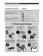
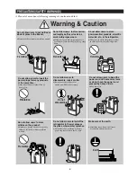
1. PRECAUTIONS(SAFETY WARNINGS)
4
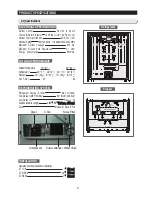
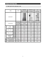
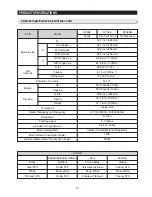
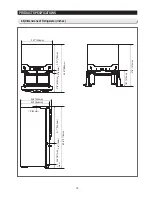
2. PRODUCT SPECIFICATIONS
7
3. DISASSEMBLY AND REASSEMBLY
19
4. TROUBLESHOOTING
39
5 . EXPLODED VIEW & PARTS LIST
72
6. PCB DIAGRAM
110
7. WIRING DIAGRAM
116
8. SCHEMATIC DIAGRAM
118
RF265/266/26NB
Summary of Contents for RF265AARS RF266AARS RF26NBRS1RF265AABP RF266AABP RF26NBBP1RF265AAWP RF266AAWP RF26NBSH1RF265AASH...
Page 2: ......
Page 19: ...18 Refrigerator PRODUCT SPECIFICATIONS 2 9 Cooling Air Circulation Freezer ...
Page 120: ...119 8 1 Whole block diagram 8 Shematic Diagram AC115V AC115V AC115V 8 1 1 MODEL RF266 BETTER ...
Page 121: ...120 Shematic Diagram AC115V AC115V AC115V 8 1 2 MODEL RF265 GOOD RF26NB ...
Page 122: ...121 8 2 CIRCUIT DIAGRAM Shematic Diagram 8 2 1 Sheet 1 of 2 ...
Page 123: ...122 8 2 CIRCUIT DIAGRAM Shematic Diagram 8 2 2 Sheet 2 of 2 ...


