background image

50

DISASSEMBLY AND REASSEMBLY

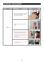
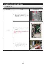
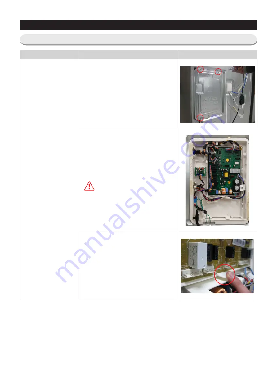
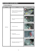
3-27) Electric Box

Part Name

How To Do

Descriptive Picture

PBA Main

1.  Remove the 2 screw attached to the upper 

left and right Case PCB Panel with a phillips 

screw).

2.  Disengage all housing connectors from the 

main PCB.

CAUTION

Before doing the above, make sure that the 

unit is unplugged.

3.  Press the lower locking hook down and 

remove the Main PBA by pulling it out. 

(Refer to the picture)

Summary of Contents for RF28R7201 AA Series

Page 1: ...SAFETYWARNINGS 5 2 PRODUCTSPECIFICATIONS 9 3 DISASSEMBLYAND REASSEMBLY 18 4 TROUBLESHOOTING 51 5 PCB DIAGRAM 97 6 WIRING DIAGRAM 100 7 BLOCKDIAGRAM 101 8 MODELCODE TABLE 102 FRENCH DOOR REFRIGERATOR MODELNAME RF28R MODLE CODE RF28R7201 AA RF28R7201 SA ...

Page 2: ...appliance may result in personal injury and property damage The manufacturerordealer cannot be responsible forthe interpretation of this information SAMSUNG ELECTRONICSAMERICA INC Technical Service Guide Copyright 2010 All rights reserved This service guide may not be reproduced in whole orin part in anyform without written permission from the SAMSUNG ELECTRONICS Company ...

Page 3: ...3 3 14 EvaporatorIn Refrigerator 34 3 15 FreezerDoor 35 3 16 Convertible Door 36 3 17 Flex Zone Door 37 3 18 Ice Maker 38 3 19 Flex Zone Light 41 3 20 FreezerLight 41 3 21 DoorSwitch In Freezer 42 3 22 EvaporatorCoverIn Freezer 43 3 23 EvaporatorIn Freezer 44 3 24 Comp tCooling Fan 45 3 25 COMPRESSOR 47 3 26 Machine Compartment 49 3 27 Electric Box 50 4 TROUBLESHOOTING 51 4 1 Function forfailure d...

Page 4: ... 2 10 When the DispenserPanel PBA does not operate normally 91 4 2 11 When refrigeratorROOM Lamp does not light up 92 4 2 12 If ICE Wateris not supplied 93 4 2 13 If Cubed orCrushed Ice is not supplied 94 4 2 14 If CoverIce Route Motor Geard Motor is not working normally 95 4 2 15 IR SensorTrouble Shooting 96 4 2 16 LED blinking frequency depending on protecting functions 97 5 PCB DIAGRAM 98 5 1 P...

Page 5: ...compared with the state before disassembly Check the use circumstance of refrigerator If the refrigeratoris installed at the place that is damp orwet orstatus of installation is unstable change the installation place Ground the refrigeratorproperly Particularly Be sure to earth when there is a risk of an electric leakage by humidity orwetness Do not use multi plugs in a plug socket at the same tim...

Page 6: ... electric shock Unplug Use the rated components on the replacement Check the correct model rated voltage rated current operating temperature and so on On repair make sure that thewires such as harness are bundled tightly Bundle tightlywires in ordernot to be detached bythe external force and then not to be wetted On repair remove completelydust or otherthings of housing parts harness parts and che...

Page 7: ...r receptable May cause abnormal generation of heat orfire Do not allowusers to disassemble repairoralter It may cause fire orabnormal operation which leads to injury Do not allowusers to bend the power cordwith excessive force ordo not have the powercord pressed byheavy article May cause fire Do not allowusers to store articles on the product Opening orclosing the doormay cause things to fall down...

Page 8: ...t as the rest of the flooring This surface should be strong enough to support a fully loaded refrigerator or approximately 660lbs 299kg MOVING Protect the finish of the flooring Cut a large section of the cardboard carton and place under the refrigerator where you are working When moving be sure to pull the unit straight out and push back in straight ...

Page 9: ...equired and are therefore more efficient Food odorfrom the refrigeratordoes not affect food in the freezerdue to separate airflow circulation Flex Zone The Flex Zone is a full width independent mid drawerwith adjustable temperature control CounterHeight Design The Independent Mid Drawer Flex zone is counterHeight to fit contemporary kitchen Secure Auto Close DoorSystem Secure Auto Close DoorSystem...

Page 10: ...ter filter is placed between crispers for changing filter conveniently without removing items from Refrigerator Internal Display The display change more wider and apply Blue LED lighting And Touch Sensor Lighting make the refrigerator graceful Independent One leverDispenser One leverforice and water ...

Page 11: ...imum Ground Path Resistance 0 1 Ohm NO LOAD PERFORMANCE Ambient Temperature 70 21 90 32 Refrigerator 34 1 46 7 34 1 46 7 Flex Zone 29 1 42 5 29 1 42 5 Freezer 8 22 8 14 8 22 8 14 Run Time 60 80 REFRIGERATION SYSTEM Refrigerant R600a 2 46oz 70g NF54M7151AN E01 BTU hr 0 372kw 1270 Compressoroil mineral 5 250cc Israel Model ML Compressor C Fan Dryer Single Condenser INSTALLATION Clearance must be pro...

Page 12: ...12 ProductSpecifications 2 3 InteriorViews applicable models only ...

Page 13: ... 140ℓ Flex Zone 3 8 Cu ft 48ℓ Refrigerator 15 9 Cu ft 418ℓ EfficiencyofVolume 60 Weight Set 328 5 Pounds 149 kg Packing 350 5 Pounds 159 kg Packing Width 381 4 Inch 972mm Depth 36 2 8 Inch 920mm Height 75 3 4 Inch 1923mm Compressor Reciprocate Rated Frequencyand Frequency AC115 V 60 Hz AA North America AC 230 V 50 Hz ML Israel Refrigerant R600a Foaming Agent C Pentane Refrigerant Input Amount 2 46...

Page 14: ...5 7 Refrigerator Model Temperature Selection ON THERMISTOR R SENSOR 502AT 34 1 36 2 38 3 40 4 46 7 48 8 Defrost Related Components Defrost Cycle First Defrost Cycle Concurrent defrost of F and R 6hr 10min Defrost Cycle FRE 12 23hr vary according to the conditions used Defrost Cycle REF 6 11hr vary according to the conditions used Pause time 12 1min Defrost Sensor F R Defrost Sensor Model THERMISTO...

Page 15: ...efrigeratorHeater AC 250V 3A Off 140 60 On 104 40 RatedVoltage AC 230V 50HZ MotorBLDC FRE DC12V 2 1W DREP5020LC MotorBLDC REF DC12V 1 92W 3612JL 04W S49 G51 MotorBLDC CIRCUIT DC12V 1 7W DRCP8020LA MotorBLDC ICE ROOM DC12V 3 2W DREP5020LB AugerMotor AC230V 102W ISG 3240SSJ Geared Motor ICE MAKER DC12V GSP 24RW 001F Geared Motor DISPENSER AC230V 3 5W MVCD18AR19 MotorDAMPER DC12V NSBY001TJ1 Lamp LED ...

Page 16: ...ations 4 102mm 36 1 2 926mm 35 6 8 908mm 34 864mm 1 1 4 30 6mm 70 1777mm 8 15 16 228mm 22 9 16 573mm 20 3 4 528mm 29 1 2 751mm 49 1 4 1254mm 22 9 16 573mm 2 51mm 1 2 13mm 2 5 Dimensions of Refrigerator Inches Model RF28R ...

Page 17: ...oductSpecifications 2 6 Optional Material Specification IMAGE Part Name Part Code AMOUNT ASSY PACKING SUB DA99 03490L 1 ASSY CASE LAMP REF DA97 12606C 1 LED LAMP FRE DA41 00676J 1 LED LAMP MID DA41 00676J 1 ...

Page 18: ...freezer When the contents freeze the glass may break and cause personal injury Do not storevolatile orflammable substances in the refrigerator The storage of benzene thinner alcohol ether LP gas and othersuch products may cause explosions Required Tools IMAGE ITEM USE Phillips Head Driver Use forassembling and disassembling of screw Flat Head Driver Use forassembling and disassembling of HomeBar D...

Page 19: ...left doorhinge To disconnect the connector more easily press the end of the hook and pull connector CAUTION Make sure unit is unplugged 3 As shown in the picture Remove watertube from hinge by holding at the both sides of the Tube Fitting and pulling it out And remove the Tube Fitting by pulling the waterhose afterpushing in the locking ring tab at the end of the Tube Fitting 4 Afterpulling the Hi...

Page 20: ...aightly up to remove CAUTION Be careful not to drop the door 6 Lift the grommet hinge straightly up to remove 7 With a Philips head screwdriver remove the screw attatched to the lowerleft and right doorhinges With a 0 4in Hex wrench remove the 2 flat head screws Remove the lowerleft and right doorhinges ...

Page 21: ...isassemblyand Reassembly 3 3 DoorHandle Refrigerator Part Name HowTo Do Descriptive Picture DoorHandle Fridge 1 Loose Set Screwwith 0 1in Hex wrench and pull front the handle 2 Remove the covervinyl of door ...

Page 22: ...rt Name HowTo Do Descriptive Picture DoorHandle Freezer 1 Loosen the Set Screw situated at the bottom right of the appliance about 0 1in by using Hex wrench 2 Pull the Set handle out by moving it to the right side CAUTION Be careful not to scratch orbreak the parts ...

Page 23: ...Water Dispenser Disassembly 1 Put both fingers in the upper of lever Pull and remover the lever slowly 2 Remove two screws under the Dispenser Display 3 Grasp the top of the dispenser display and pull it down CAUTION Be careful notto scratch orbreakthe parts 4 Disengage the wiring connector of display cover ...

Page 24: ...nser Disassembly 5 Put both fingers in the upper of lever Pull and remover the lever slowly 6 Pull to the front direction cam to separate the ASSY CASE ICE ROUTE from dispenser 7 Put gloves and separate the ASSY CASE ICE ROUTE with pulling according to the arrow direction 8 Remove connector ...

Page 25: ... Do Descriptive Picture Glass Shelf Remove the shelf by lifting the front part of the shelf up and pulling it out 3 7 Foldable Glass Shelf Part Name HowTo Do Descriptive Picture Foldable Glass Shelf 1 Remove the Cap 2 Remove 2 screws of the Folderble Glass Shelf ...

Page 26: ...ble Fruit Shelf 1 Remove the vegetable fruit drawerby pulling the rollerpart and lifting it up 2 While pressing the button on the left of the shelf in txhe picture lift up the Vegetable Fruit DrawerShelf Referto the picture button 3 Remove the vegetable fruit drawershelf by pulling it out Referto the picture ...

Page 27: ... all drawers and shelves 1 Remove the 3 screws holding down the Top Table and remove the Top Table 2 a Remove CoverTube Fitting b Remove the Watertube blue from the tube fitting by pushing in on the locking ring and pulling out the tube 3 Remove three screws securing the water tubes 4 a Pull the Waterblue hose out b Push the Tube Fitting and pull the grey hose out ...

Page 28: ...8 Disassemblyand Reassembly Part Name HowTo Do Descriptive Picture CaseWaterFilter 5 Disconnect the 2 Housing connectors 6 Remove a screw the case fitlerright side 7 Lift and pull the Case WaterFilterout ...

Page 29: ... MotorDamper Part Name HowTo Do Descriptive Picture MotorDamper 1 Remove the 2 screws underthe waterfilter case and take off the coverdamper 2 Disengage 2 housing connector 3 Take off the MotorDamperby pulling a flat blade screwdriver ...

Page 30: ...iltercount clockwise Referto the picture 2 Remove the waterfilterby pulling it Referto the picture 3 Push the waterfilterdirectly 4 Turn the waterfilterclockwise until it locked CAUTION Be sure to flush the dispenserthoroughly approx 6 to 7 minutes otherwise watermay drip from the dispenser This means that there is still airin the line ...

Page 31: ... Vertical Hinged Section Part Name HowTo Do Descriptive Picture Vertical Hinged Section 1 Remove 2 screw cap parts with a flat blade screwdriver Referto the picture CAUTION Be careful not to scratch orbreak the parts 2 Unscrew 2 screws ...

Page 32: ...sembly Part Name HowTo Do Descriptive Picture Vertical Hinged Section 3 Disengage the internal housing connectorof the vertical hinge 4 Remove the vertical hinged section by lifting the vertical hinge up Referto the picture ...

Page 33: ...e picture CAUTION Be careful not to scratch orbreak the parts 2 Unscrew 4 screws 3 Remove the the lowerpart of angle mid by pulling it out and pushing it down Referto the picture 4 Remove the hook by pulling it from the lower part and pushing the coverdown Referto the picture 5 Disconnect the 2 housing connectors Referto the picture CAUTION Continues a work afterconfirming that fan operation stops...

Page 34: ...ve the the housing coverby pushing both lateral sides of the housing cover and pulling it out Referto the picture 2 Disconnect the housing connectorpart on left side Referto the picture 3 Disconnect the housing connectoron right side 4 Remove the evaporatorby lifting the bottom side of it up and pulling it out Referto the pi cture ...

Page 35: ...system 3 Afterlifting the FreezerGuard up holding both sides remove it at the rail system CAUTION The box may get scratch on its side by getting twisted left and right when disassembling the drawerbox 4 Press the fixing hook of rail system 5 Afterholding and pulling out the top of FreezerDoor remove it at the rail system CAUTION Make sure there is no scratch at the end of Sliding Rail by being den...

Page 36: ...ull the and remove the convertible room by pulling it to yourbodywith both hands open to full extension 2 Remove the coverhousing by a flat blade screwdriver 3 Disengage the housing 4 Unscrew 4 bolts 2 bolts each on the both sides 5 Lifting up the convertible door remove the convertible doorfrom the rail ...

Page 37: ...37 Disassemblyand Reassembly 3 17 Flex Zone Door Part Name HowTo Do Descriptive Picture Mid drawer 6 Remove the shaft gear by pull the pin out 7 Remove the screw and pull out The rail ...

Page 38: ...2 Press TESTKEY to change the test function in the orderof Manual operation 3600 RPM Manual operation 3600 RPM OF r manual R defrost rd manual F R defrost Fd cancel normal operation forced operation If the key on the front panel does not operate within15 seconds of switching to TEST Settings MODE it is deactivated and switches to the previous DISPLAY mode 3 Lift up the Ice Bucket and pull it out 4...

Page 39: ...erHousing Connector 7 Remove the screwfrom the Duct Tray ice 8 With a flat blade screwdriver push the duct to the right and remove it from the locking tab Referto the image 9 With a flat blade screwdriver pry down on the refrigerant tube to separate it from the bottom of the ice maker Referto the image ...

Page 40: ...MakerAssembly completely 11 While pressing the Hook pull out the Ice Maker 12 While pushing down the Duct Tray Ice pull out the Ice Makercarefully and remove it When removing the ice maker be careful not to damage the grommets on the tray orthe refrigerant tube Refertothedottedpartsontherightsidephoto If the ice makeris frozen it can be melt by using the steam heater ...

Page 41: ...e Picture Flex Zone Light 1 Remove the coverFlex zone lamp by a flat blade screwdriver 2 Disengage the housing 3 20 FreezerLight Part Name HowTo Do Descriptive Picture FreezerLight 1 Remove the coverFreezerlamp like the way disassembling the Flex zone lamp 2 Disengage the housing ...

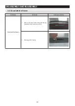
Page 42: ...ssemblyand Reassembly 3 21 DoorSwitch In Freezer Part Name HowTo Do Descriptive Picture DoorSwitch In Freezer 1 Remove the coverFreezerlamp like the way disassembling the Flex zone lamp 2 Disengage the housing ...

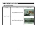
Page 43: ...r Part Name HowTo Do Descriptive Picture EvaporatorCoverIn Freezer 1 Remove the freezerdoorand freezerdrawerby pulling out the drawerand then unscrewing 2 screws 2 Lift up the evaporatorcover 3 Disengage the 3 housing connectors and remove the evaporatorcover ...

Page 44: ...ssembly 3 23 EvaporatorIn Freezer Part Name HowTo Do Descriptive Picture EvaporatorIn Freezer 1 Remove the housing connectorpart left one 2 Remove the evaporatorby pulling the lower part of the evaporatorwhile lifting it up ...

Page 45: ...d Reassembly 3 24 Comp tCooling Fan Part Name HowTo Do Descriptive Picture Comp Cooling Fan 1 Unscrew 7 point of Covercomp 2 Remove the DRAIN HOSE 3 Remove1 screw 4 Disengage the HOUSING CONNECTOR Refer to the picture ...

Page 46: ...emblyand Reassembly Part Name HowTo Do Descriptive Picture Comp Cooling Fan 5 Pull it forward and lean against the DRAIN HOSE 6 Rotate it based on the PIPE 7 The FAN is disassembled Assembly it in reverse order ...

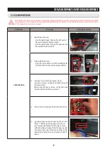
Page 47: ...l smooth Use the Sand Paperto make the right part of the welded metal smooth 2 Pipe Cutting Process Using the pipe cutter cut both welded parts Straight section should be at least 25mm 3 Connect Suc Bending process Bend Connect and Suc to make a straight line with the Comp Pipe Make sure Connect and Suc do not interrupt the Fan afterthe Bending process NG OK 4 Check Service Ring specifications of ...

Page 48: ...ice ring into the Connect Suc pipe and fasten it by screwing it 360 2 times 7 Installing manual Lokring Tool Install manual Lokring Tool on the Service Ring 8 Fastening Service Ring Press the ring with the Lokring tool When fastening press the ring multiple times slowly untill the ring is fastened in the middle DO NOTPRESS ITONCE TO THE END 9 Check the Service Ring connection status ...

Page 49: ...49 Disassemblyand Reassembly 3 26 Machine Compartment Part Name HowTo Do Descriptive Picture RelayO L 1 Disengage the housing connector 2 Remove CoverRelay 3 DisassembleHousingConnectorfromComp ...

Page 50: ...e 2 screw attached to the upper left and right Case PCB Panel with a phillips screwdriver 2 Disengage all housing connectors from the main PCB CAUTION Before doing the above make sure that the unit is unplugged 3 Press the lowerlocking hook down and remove the Main PBA by pulling it out Referto the picture ...

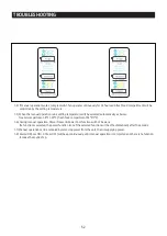
Page 51: ...al operation function 1 1 If any key is pressed once in test mode blinks FF on the display and it indicates the refrigeratorhas entered the manual operation At this moment buzzerbeeps as an alarm 1 2 If any key is pressed once at the manual operation1 status OF rwill be displayed FF and OF rmeans manual operation 1 and 2 separately These 2 functions operate with same RPM of COMP 1 3 If manual oper...

Page 52: ...ercompartment 8 23 fresh food compartment 34 1 1 6 During manual operation PowerFreezer PowerCool function will not be work If a function is selected the powerfunction icon of the selected function will be off automatically after10 seconds 1 7 Manual operation can be canceled by removing powerfrom the unit then resupplying power 1 8 Alarm 0 25 sec ON 0 75 sec OFF will beep continuously until manua...

Page 53: ...R Defrost will be performed at the same time 2 3 At this time itwill send out Beep sound for2 seconds and then itwill perform Forced F R Defrostwhile sending out 0 5 sec On and 0 5 sec Off sound 3 Test cancel mode 3 1 During the simultaneous defrosting of fresh food and freezercompartments if the display panel change to the test mode and test button is pressed one more time defrosting of fresh foo...

Page 54: ...ferto self diagnostic CHECK LIST 1 3 Self diagnostic button is recognized onlywhen the erroris displayed by the bad sensor Display does not operate normally but temperature control will be controlled by the emergency operation 1 4 When the erroris detected by self diagnosis the errorcan be canceled automatically if all troubled sensors are corrected orSelf diagnostic function key Fridge Key FlexZo...

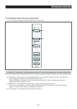
Page 55: ... pressed simultaneously for10 seconds including above 4 seconds selfdiagnostic function will be selected 2 3 At this moment self diagnostic function will be returned with buzzersound ding dong If there is an error display of errorwill be operated for30 seconds and then return to normal condition whether problem is corrected ornot Referto self diagnosis CHECK LIST 2 4 Input by button is not accepte...

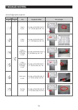
Page 56: ...or ThevoltageofMAINPCBCN20 9 11 shallbebetween4 5V 1 0V Freezer compartment defrosting sensor ThevoltageofMAINPCBCN20 6 8 shallbebetween4 5V 1 0V Fridge compartment defrosting sensor ThevoltageofMAINPCBCN20 5 7 shallbebetween4 5V 1 0V External air sensor ThevoltageofMAINPCBCN60 3 5 shallbebetween4 5V 1 0V Flex Zone sensor ThevoltageofMAINPCBCN40 18 20 shallbebetween4 5V 1 0V ...

Page 57: ...or ThevoltageofMAINPCBCN90 14 24 shallbebetween4 5V 1 0V Ice Room SensorError ThevoltageofMAINPCBCN90 2 4 shallbebetween4 5V 1 0V FreezerFan Error ThevoltageofMAINPCBCN20 16 18 shallbebetween7V 12V Fridge Fan Error ThevoltageofMAINPCBCN20 15 17 shallbebetween7V 12V C Fan Error TheThevoltageofMAINPCBCN40 11 13 shallbebetween7V 12V R Self diagnostics check list ...

Page 58: ... Error AfterseparatingMAINPCBCN40 wirefromPCB resistancevalue betweenCN40 25 27 shallbe 135ohm 7 Resistancevalueis variedbyinputpower 0ohm heatershort ohm wire bimetalopen Mustpoweroff IceMaker Fridge FunctionError AfterchangingtheIceMaker R plug therefrigeratorpowercodeagain andchecktheoperation IceRoomFam Error ThevoltageofMAINPCBCN20 22 24 shallbebetween7V 12V Main Panel Communication Error Act...

Page 59: ...er 0ohm heatershort ohm wire bimetalopen Mustpoweroff FridgeIceRoom HeaterError AfterseparatingMAINPCBCN20 wirefromPCB resistancevalue betweenCN20 19 23 shallbe 135ohm 7 Resistancevalueis variedbyinputpower 0ohm heatershort ohm wire bimetalopen Mustpoweroff TheFreezer compartment abnormalhigh temperature indicatorblinks Checkifthedoorhasbeenopenfor alongtimeorifhotfoodhasbeen storedinthecompartmen...

Page 60: ...M FaultError Complocation detectionerror ChecktheCompressorconnections CheckthevoltageofResistanceofR2 0 09Ohm Checkthesolderingstatusofthe MAINPCB Checkifanypartshave short circuited ChecktheCompressorandtheCycle Compmotor constrainterror CompressorlockingError ChecktheCompressorandtheCycle Checkthecompressorwire connections Complowvoltage error Checktheinputvoltage AC60V InputPowerAC110 127V AC1...

Page 61: ...diagnostics check list LED Item Diagnostic method Location image F R CompIPMShut DownError Checkthesolderingstatusofthe inverterPCB Checkifanypartshave short circuited CheckiftheDC15Voutputisless than13 5V ChecktheCompand Cycle ...

Page 62: ...ws the load that micom signal is outputting However It means that micom signal is outputting it does not mean whetherload is operating ornot That is to say that though load operation is displayed load could not be operated by actual load errororPCB relay erroretc This function would be applied at A S 4 Load condition displayfunction will maintain for30 seconds and then normal condition will be ret...

Page 63: ...63 TROUBLESHOOTING ⓐ ⓑ ⓒ ⓓ ⓔ ⓕ ⓖ R 10 F 10 R 1 F 1 ...

Page 64: ...sponding LED is blinked 14 Comp F 1 a In the case of the Comp operation the corresponding LED is blinked 15 F FAN HIGHEST F 1 b c In the case of the F FAN HIGHESToperation the corresponding LED is blinked 16 F FAN HIGH F 1 b In the case of the F FAN HIGH operation the corresponding LED is blinked 17 F FAN LOW F 1 c In the case of the F FAN LOW operation the corresponding LED is blinked 18 F compar...

Page 65: ...elected blinks O FF on the temperature setting display of the panel and it indicates the refrigeratorhas entered the Cooling Off mode 4 During Cooling Off mode if Fridge orFreezerorFlexZone compartments sensors are higherthan149 65 Cooling Off mode will be canceled automatically and freezing operation will be returned There is no buzzersound when the Cooling Off mode is canceled by the temperature...

Page 66: ...or oF for5 seconds on the temperature setting display of the panel and it indicates the refrigeratorhas entered orexited the Exhibition mode After5 seconds the display panel will work normally 4 During Exhibition mode if fridge orfreezerorflex zone compartments sensors are higherthan149 F 65 C Exhibition mode will be canceled automatically and freezing operation will be returned There is no buzzer...

Page 67: ...econds In that case you may take yourfingers off both buttons and press the Fridge button to enterthe Option Setting Mode KEY operation method forchanging to option mode Press the Fridge and FlexZone buttons simultaneously for6 seconds All On Off will blink with 0 5sec interval 4seconds If take the fingeroff from above keys and press Fridge Key Option setting mode will be started ...

Page 68: ...e Value Up Reference Value Down Code Code Change Rotation KEY control method afterconverting to option mode Key control in option mode DoorAlarm Key Code Change Key Rotation FlexZone Key Reference Value down key Fridge Key Reference Value Up key ...

Page 69: ...trolled 4 2 C less than setting temperature in the display Note Basically all the data in option has cleared from the factory Therefore almost all setting value are 0 But some setting values could be changed forthe purpose of improving performmance NOTE You need to check the product manual and orspecification 2 Afterchanging to the option mode fresh food compartment 0 freezercompartment 0 will be ...

Page 70: ...y temperature notch gap bytemperature etc 5 Option function is set in the EEPROM at shipping process in the factory You would betternot to change the option of yourown Completing the setting is that option function return to normal display after20 seconds Do not turn off the appliance before returning to the normal display mode Note Option setting function exists in the otheritems We will skip the...

Page 71: ... Reference Value Fridge Room 7 SEG 0 Set item fresh food Temp Shift Reference Value Fridge Room 7 SEG 1 Setting value Temp compensation FZ compartment Code 0 0 0 0 1 1 0 5 2 2 1 0 3 3 1 5 4 4 2 0 5 5 2 5 6 6 3 0 7 7 3 5 8 1 0 5 9 2 1 0 10 3 1 5 11 4 2 0 12 5 2 5 13 6 3 0 14 7 3 5 15 8 4 0 Setting value Temp compensation FZ compartment Code 0 0 0 0 1 1 0 5 2 2 1 0 3 3 1 5 4 4 2 0 5 5 2 5 6 6 3 0 7 ...

Page 72: ...the mid drawerroom temperature to 2 1 Set item DispenserHeaterRate Reference Value Fridge Room 7 SEG 19 Set item Pantry Mid DrawerRoom Temp Shift Reference Value Fridge Room 7 SEG 20 Setting value Rate change FZ compartment Code 0 0 0 1 20 operation up to100 Setting value Temp compensation FZ compartment Code 0 0 0 0 1 1 0 5 2 2 1 0 3 3 1 5 4 4 2 0 5 1 0 5 6 2 1 0 7 3 1 5 Reference Value Code Refe...

Page 73: ... Amount of WaterSupply Reference Value Fridge Room 7 SEG 32 Set item Ice MakerStandby Time Reference Value Fridge Room 7 SEG 33 Setting value Amount of watersupply FZ compartment Code 0 setting value 1 Setting value 10cc 2 3 4 5 6 7 Setting value Temp compensation FZ compartment Code 0 14 min 1 13 min 2 12 min 3 11 min 4 10 min 5 15 min 6 16 min 7 17 min 8 18 min 9 19 min 10 20 min 11 21 min 12 22...

Page 74: ...t item Ice Room Temp Shift Reference Value Fridge Room 7 SEG 34 Set item Ice MakerDropping Temperature Reference Value Fridge Room 7 SEG 35 Setting value Temp compensation FZ compartment Code 0 13 1 12 2 11 3 10 4 14 5 15 6 16 7 17 Reference Value Code Reference Value Code Setting value Temp compensation FZ compartment Code 0 0 0 0 1 1 0 5 2 2 1 0 3 3 1 5 4 4 2 0 5 5 2 5 6 6 3 0 7 7 3 5 8 1 0 5 9 ...

Page 75: ...37 4 2 700 11741 4 39 2 2 649 11271 5 41 2 599 10823 6 42 8 2 548 10395 7 44 6 2 498 9986 8 46 4 2 449 9596 9 48 2 2 399 9223 10 50 2 350 8867 11 51 8 2 301 8526 12 53 6 2 253 8200 13 55 4 2 205 7888 14 57 2 2 158 7590 15 59 2 111 7305 16 60 8 2 064 7032 17 62 6 2 019 6771 18 64 4 1 974 6521 19 66 2 1 929 6281 20 68 1 885 6052 21 69 8 1 842 5832 22 71 6 1 799 5621 23 73 4 1 757 5419 24 75 2 1 716 ...

Page 76: ...34 1903 35 1930 36 1957 37 1984 38 2011 39 2038 40 2065 41 2092 42 2119 43 2146 44 2173 45 2200 46 2227 47 2254 48 2281 49 2308 50 2335 51 2362 52 2389 53 2416 54 2443 55 2470 56 2497 57 2524 58 2551 59 2578 60 2605 61 2632 62 2659 63 2686 64 2713 65 2740 66 2767 67 2794 RH Output mV 68 2821 69 2848 70 2875 71 2902 72 2929 73 2956 74 2983 75 3010 76 3037 77 3064 78 3091 79 3118 80 3145 81 3172 82 ...

Page 77: ...4 White and 13 Pin CN90 from PCB ICE Room CN90 2 GRY and 13 Pin CN90 from PCB ERROR Code Bad contact of connector insert correctly Is MAIN PCB Connector CN90 inserted correctly Is ICE MakerSensor unit normal Isthevoltage between MAIN PCB Connector CN90 14 White and 13 Pin CN90 from PCB normal Is inputvoltage of IC01 MICOM 14 normal Start NO YES YES YES YES Replacethetemperature sensor NO Recheckth...

Page 78: ...resistance Measuringvoltage R IC01 MICOM 5 CN20 9 W YEL and 11 Pin CN20 R DEF IC01 MICOM 3 CN20 5 YEL and 7 Pin CN20 F IC01 MICOM 7 CN20 10 YEL and 12 Pin CN20 F DEF IC01 MICOM 6 CN20 6 BLU and 8 Pin CN20 Mid IC01 MICOM 2 CN40 18 W YEL and 20 Pin CN40 Ambient IC01MICOM 12 CN60 5 W BLU and 16 Pin CN60 from PCB typical Ground part are similar Check the measure on the voltage of Resistance R210 R R20...

Page 79: ...on PCB orCN60 5 W BLU and 16 Pin CN60 from PCB Comparethetemperaturetableafterthemeasure Measuringvoltageof R R210 IC01 MICOM 5 on PCB orCN20 9 W YEL and 11 Pin CN20 R DEF R209 IC01 MICOM 3 on PCB orCN20 5 YEL and 7 Pin CN20 F R224 IC01 MICOM 7 on PCB orCN20 10 YEL and 12 Pin CN20 F DEF R223 IC01 MICOM 6 on PCB orCN20 6 BLU and 8 Pin CN20 Mid R427 IC01 MICOM 2 on PCB orCN40 18 W YEL and 20 Pin CN4...

Page 80: ...nsorTable Replacethe HumiditySensor No Recheckthe PCB Wire Terminal connection NO 0 6V Measurement 4 6V Checkthe iced solder solder bringing disturbed solder Exchangethe PCB NO Notroublewith PCBtemperature sensor Recheckthe bad contact ofthe connection Start YES YES YES ERROR Code Sensor MICOM Connector number Humidity Connector CN30 3 brown to J23 JUMMPER PCB typical Ground Voltage measured betwe...

Page 81: ...place Heater Is DamperHeater normal about135ohm Isthe inputvoltage of IC01 MICOM 91 normal Start YES YES YES Bad contact of connector insert correctly NO 1 Recheckthewire 2 Replace PCB MAIN NO NO Normal recheck Start YES YES YES Is MAIN PCB connector CN40 inserted correctly MeasurethevoltageofResistance between 25 27after CN40connectoropen 1350ohm 7 MICOM 91 condition Initialpower On Heateroff Wor...

Page 82: ...tion willrestartfourtimesmore Ifsignalsarenotenteredcontinuously themotor willberestartedafter10Minutes Thisfunctioniseffectivewhenthenormal operationofmotorwouldberestrainedbyforeignmatterssuchasice ThevoltagebetweenPCBtypicalGroundCN20 17 Pinand FFAN CN20 16 S RED shallbelessthanDC7 12V RFAN CN20 15 S BLU shallbelessthanDC7 12V CFAN CN40 13 S BLU shallbelessthanDC7 12V Recheckifresistancevaluesa...

Page 83: ...rmotorturns on As the Ice makermotorturns on TESTMODE COUNToperates 6 minutes count Condition Ambient temperature 32 75 Notch 2 38 19 0 3 3 Initial full of ice bucket capacity 794 g 58ea Start Executemanualoperation No Yes Yes No Yes Yes No No IsCOMPRESSORON IstheIce Roomtemperaturesuitablefor theFanworking PredictedCause FAN MOTORtroublesitself Badwiringconnections WrongInputofthefanmotorrotation...

Page 84: ... 3 Check ReplaceMAINPCB 1 Check ReplaceWaterValve RefertoWaterValveOperatingConditions 2 Check ReplaceMainPCB 1 Check RepairICEMakerSensor RefertoitwhenICEMakerSensorisdefective PCB Ice MakerRelated Parts are normal Check alltheWire Connections again Yes No Yes No Yes No Yes No Displays ERROR Code 1 Waterwill be automatically supplied to the Ice Makerdepending on temperature time conditions and ic...

Page 85: ...DEF CN70 3 WHT CN71_1 5 BLK Recheck if resistancevalues are different afterthe test Measuringpointofresistancevalueaccordingtosensor F DEF CN20 6 8 measuring resistance value R DEF CN20 5 7 measuring resistance value 0Ω Short trouble Ω Open trouble Measuringpointofresistancevalueaccordingtoheater F DEF CN70 5 BRN CN71_1 5 BLK measuring resistancevalue 63 ohm 7 R DEF CN70 3 WHT CN71_1 5 BLK measuri...

Page 86: ...cted No Yes ReplacethePCBASSY ChecktheMAINPBA 12V bothendsofC1006 5V CN90 2 28 Does theSMPSdelivernormaloutput voltagesof12V and5V No Yes CheckingconnectionofmainPCB Checkingconnectionbetween upperhingeanddoor CheckingconnectionofdoorpanelPCB DoesthePanelPCB functionproperly No Yes 1 ResolderthePCB 2 ReplacethePCBMAIN Isthereany solderingshortorpoorsolderingjob detectedonPCB No Yes Normal 4 2 6 Wh...

Page 87: ...gedproperly ReplaceCOMPASS Y No No 0 800Hz50 DutySignalOutput ChecktheNoiseFilter PowerCord Makesuretheconnectoris pluggedproperly No No Repairthesensingpart orReplaceMAINPBA No Yes Yes Yes Yes Yes Yes Yes Yes Yes Yes When ForcedOperationmodeis activated COMP operates IsDC15Vappliedto ZD501 Is AC115Vappliedto CN81 COMP Connector CN102 is Good IsDC5Vappliedto C1009 No COMPASS YisGood F SensorisGood...

Page 88: ...cswitch Itcanbeoperatedwhendoormagnetis combinedwithit Start Removecausesaftercomprehendingthe conditionsofinterferanceby doorgasket foodetc No Replace DoorS W No Replace DoorS W No MAIN PCB DoorS Wis normal Recheck and replace Panel PBA No Connectoris not inserted Repair disconnect part Repairwire connection and DoorS W No Yes Yes Yes Yes Yes Is doorclosed completely Iswater penetrated intothe do...

Page 89: ...nontheinnerpanel fridgeroom Isthe connectionbetweeninnerpanel PBACN01andCabiWireHarness normal Isthe connectionbetweenBUZZERPBA CN1andAssyTopTableWireHarness normal MAINPCBnormal BUZZERnormal CheckConnectorContactDefect CheckConnectorContactDefect Recheckthebuttonpressingforce andmechanicalproblem Yes No No No Yes Yes Start ...

Page 90: ...eWireCut andtheWireShort ChecktheWireCut andtheWireShort MAINPCB Connector CN40 isinserted normally Yes ThePanel PCBConnecterisconnected properly Yes Whenreplacing Panel PCB itlightsup No Buttonsgetstuck beingpresseddown No Buttonsgetstuck beingpresseddown No Buttonsgetstuck beingpresseddown No No InsertMAINPCBConnectoragain No InsertConnectoragain Repairthecontacttrouble Yes ReplacePanelPCB Yes R...

Page 91: ...nector ChecktheWire Cut andtheWire Short No No No No No Yes Yes Yes Start Buttons getstuckbeingpressed down Buttons getstuckbeingpressed down Buttons get stuck being pressed down Re assemblePCBASS Y orcleartherestriction Re assemblePCBASS Y orcleartherestriction ReplacePanelPCB Checkthe DispenserPanel Connectors ChecktheWire Cut andtheWire Short Checkthewire connection Cabinet ChecktheWire Cut and...

Page 92: ...tandLeft Close 0V Low Open 5V High MICOMState Door FF FZ MID 58 60 15 Close 0V Low 0V Low Open 5V High 5V High Q408 R Q404 F IC905 2 MID State IC Q408 R Q404 F IC905 2 MID 0V Low 0V Low 5V High 11 12V High 4 2 11 When refrigeratorROOM Lamp does not light up 1 Measuring outputvoltage F LED CN40 10 W RED and CN40 12 GRY R LED CN40 26 RED and CN40 28 GRY MID LED CN60 19 W RED and CN40 22 W BLK Checki...

Page 93: ...ormal MAINPCBnormal Needtochecktheotherparts CheckthewirebetweenIcewatervalve MAINPCB Icewatervalveitselfhastroubleorbadcontactofconnector Checktheconnectionhose Normal CheckIcewatervalvehose Checksolderingshort ReplacePCB Checksolderingshort ReplacePCB Checksolderingshort ReplacePCB Checksolderingshort ReplacePCB NO YES YES NO NO NO NO NO YES YES Checking method ofvoltage Based on 1 Check thevolt...

Page 94: ...Wselfdiagnosis Checktheconnectingwires MAIN PCBfailure Replace Is MICOM IC01 55 change into 0Vwhen press Ice switch No Is the Dispenser Coveropened No ReplacetheMAINPCB ErrorsonIC01 Is IC72 2 3 changed into 5Vwhen pressing Ice Switch No RY7 RY7DRELAYError ReplacetheMAINPCB Afterdisconnecting the CN71_1 measure The both ends of Contact points RY7 Afterdisconnecting the CN71_1 measure The both ends ...

Page 95: ...Motorwill rotate continuouslywhen the MotorSwitch is not sensed Main PCB Check thewire OPEN SHORTbetween the CoverIce MotorRotation sensing switches Check the Short of CoverIce MotorControl Circuit SSR73 in the MAIN PCB Replace the MAIN PCB orthe DispenserCoverMotor Is the AC inputvoltage applied to the both ends of the motor Yes No Check Repairthe Housing connector Is the sensing SWITCH connectio...

Page 96: ...with the Fridge Doorbeing open and the Ice Bucket being removed EmitterNormal EmitterDefect 4 2 15 IR SensorTrouble Shooting IndicatorLocation forIce Full in Fridge Blinking Ice Full Keep On Not Ice Full IceFullinFridgeRoom TheEmitterison Fridge ChangestoIceFull RemovetheIceBucketandturn ontheLoadStatusDisplayFunction TakeaphotooftheEmitterwith theCellPhone ReceiverDefect ReceiverNormal EmitterNor...

Page 97: ...d W phase CN04 2 Short among IPM Pins No 1 26 3 Drop the IPM operating Voltage underDC13 5V 4 Othercases check the COMP cycle etc IPM Fault Abnormal Current Detection 1 Open the COMPwire CN04 2 Bad condition of R1 ex Bad soldering 3 Othercases check the COMP cycle etc MotorLocked OverRPM 1 Operating the locked rotorCOMPwithin 5 second 2 Operating the COMP under1000 RPM more than 5 second 3 Occurth...

Page 98: ...98 5 PCB DIAGRAM 5 1 PBALayoutwith part position ...

Page 99: ...very kinds of data 6 Micom control the regrigeratorCeramic resonator generate the basic frequency of Micom operation Reset IC make Micom reset if input voltage of Micom is detected less than the specified voltage 7 Operate ICE MAKER supply powerto MOTOR and sense the variation of switch 8 Main Micom Panel Micom serial communication circuit Dispenseroption input part Water CoverIce route switch 9 A...

Page 100: ...UTO FILL VALVE GND 25 27 DAMPER H T 12V 26 28 FF ROOM LAMP GND CN20 1 3 FF DOOR S W GND 2 4 FZ DOOR S W GND 5 7 FF DEF SENSOR GND 6 8 FZ DEF SENSOR GND 9 11 FF SENSOR GND 10 12 FZ SENSOR GND 13 FF FAN FEEDBACK 14 FZ FAN FEEDBACK 15 17 FF FAN SIGNAL GND 16 18 FZ FAN SIGNAL GND 19 ICE ROOM HEATER 20 ICE ROOM FAN FEEDBACK 21 ICE PIPE HEATER 22 24 ICEROOM FANSIGNAL GND 23 12V CN70 1 FRENCH DISPENSER H...

Page 101: ...101 6 WIRING DIAGRAM This document can not be used without Samsung s authorization ...

Page 102: ...102 7 BLOCKDIAGRAM This document can not be used without Samsung s authorization 7 1 Whole block diagram 7 1 1 MAIN BLOCK ...

Page 103: ...7 SR Real Stainless 6 3DFDR Premium급 6 F Hub FDSR 6 Recess Metal SL ALF 5 3DFDR Mass급 5 F Hub 5 Arc Metal 4 33 4DFDR 4 DoubleFDSR 4 TwinI M 3 33 3DFDR 3 FDSR 3 Internal Camera 2 30 FDR 2 W IDispenser 2 1 MultiDoor 1 Internal Dispenser 1 Recess 0 중국향FDR 0 NonDispenser 0 Arc example PJT Digit Sub 1 2 3 4 5 6 7 8 9 10 11 12 13 AW3 F L Basic SEA R F 2 8 R 7 2 0 1 S R A A RF28R7201SR AA AW4CD F L FDSR ...

Page 104: ...ision 2019 Printed in Korea This Service Manual is a propertyof Samsung Electronics Co Ltd Anyunauthorized use of Manual can be punished underapplicable International ordomestic law Europe CIS Mideast Africa gspn1 samsungcsportal com Asia gspn2 samsungcsportal com North Latin America gspn3 samsungcsportal com China china samsungportal com ...

Reviews: