93
TROUBLESHOOTING
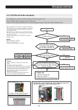
1. Please shut the water supplying prior to repair.
2. Power is applied to the one end of wires. Be careful when disassembling not to get an electric shock.
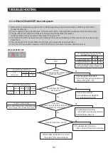
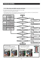
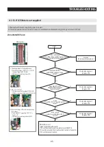
4-2-12. If ICE Water is not supplied
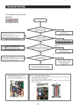
2) Ice Water(R) Valve
PIN Number
Start
Is the confirming
sound of the valve operation heard when
Ice maker test switch pushed?
Does Main PCB IC01
MICOM #90 voltage change
5V/0V?
Does Main PCB IC01
MICOM #88 voltage have
high(5V) output?
Does
Main PCB IC72-"11" have about 0.7V
output?
Is the contact
point of main PCB RELAY RY77
normal?
MAIN PCB normal.
- Need to check the other parts
①
Check the wire between Ice water valve
↔
MAIN PCB
②
Ice water valve itself has trouble or bad contact of connector.
③
Check the connection hose.
Normal
(Check Ice water valve hose.)
Check soldering short
/Replace PCB.
Check soldering short
/Replace PCB.
Check soldering short
/Replace PCB.
Check soldering short
/Replace PCB.
NO
YES
YES
NO
NO
NO
NO
NO
YES
YES
☞
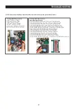
Checking method of voltage Based on
1) Check the voltage of IC72-"6"
↔
IC72-"8"
(same voltage as IC01 "#88)
- ICE Water valve waiting (about 0V)
2) IC72-"11"
↔
IC72-"8"
- ICE Water valve Waiting (about 12V±0.8V)
- ICE Water valve Operating (about 0.7V±0.5V)
3) Check the voltage of Water Valve operating
(AC voltage)
=> The Relay RY77 operating.CN71-"5"
↔
CN71_1-"5"
- ICE Water valve waiting (about AC 0V)
Summary of Contents for RF28R7201 AA Series
Page 12: ...12 ProductSpecifications 2 3 InteriorViews applicable models only ...
Page 63: ...63 TROUBLESHOOTING ⓐ ⓑ ⓒ ⓓ ⓔ ⓕ ⓖ R 10 F 10 R 1 F 1 ...
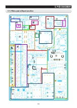
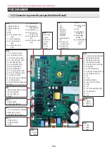
Page 98: ...98 5 PCB DIAGRAM 5 1 PBALayoutwith part position ...
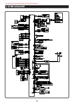
Page 101: ...101 6 WIRING DIAGRAM This document can not be used without Samsung s authorization ...

