11
2. PRODUCT SPECIFICATIONS
●
●
A newly developed SAMSUNG bottom mount freezer in 2010 has the following
characteristics.
2-1) Introduction of Main Function
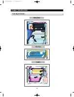
Surround Multi Flow
●
●
Uniform cooling for each shelf and even in corner in fresh
food compartment by centerpositioned fan and duct with
multiple flow effluences.
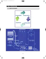
Twin Cooling System
●
●
The refrigerator and the freezer have two evaporators.
Given this independent system, the freezer and the
refrigerator are cooled individually as required and are,
therefore, more efficient.
Food odor from the refrigerator does not affect food in the
freezer due to separate air flow circulation.
Counter Height Design
●
●
The Independent Mid Drawer(Flex zone) is counter
Height to fit contemporary kitchen.
Two Lever Dispenser
●
●
Two lever dispenser can be get ice or water easily.
Secure Auto Close Door System
●
●
Secure Auto Close Door System
●
●
Cool tight doors
●
●
Energy saving
●
●
Preventing sweat on fridge doors
Flex Zone
●
●
The Flex Zone is a full-width independent mid drawer with
adjustable temperature control.
AW3 SM-EN 2011.3.31 2:50 PM 페이지11 in
Summary of Contents for RF4287HARS
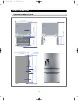
Page 17: ...18 PRODUCT SPECIFICATIONS 2 5 Dimensions of Refrigerator Inches AW3SM EN2011 3 312 52PM 18 in...
Page 86: ...87 TROUBLESHOOTING IPM FREEWHEELING DIODE VOLTAGE VALUE AW3SM EN2011 3 312 56PM 87 in...
Page 96: ...97 TROUBLESHOOTING SPM Internal DIODE Voltage AW3SM EN2011 3 312 56PM 97 in...
Page 98: ...99 TROUBLESHOOTING INVERTER PCB Circuit Diagram AW3SM EN2011 3 312 56PM 99 in...
Page 124: ...125 7 1 Model RFG295AA BETTER 7 WIRING DIAGRAM BLU BLU AW3SM EN2011 3 312 57PM 125 in...
Page 125: ...126 7 2 Model RF4287AA BEST 7 WIRING DIAGRAM AW3SM EN2011 3 312 57PM 126 in...
Page 126: ...127 7 3 Model RFG299AA 7 LCD 7 WIRING DIAGRAM BLU BLU AW3SM EN2011 3 312 57PM 127 in...
Page 127: ...128 7 4 Model RFG294AA SEARS 7 WIRING DIAGRAM AW3SM EN2011 3 312 57PM 128 in...
Page 129: ...130 8 SCHEMATIC DIAGRAM 8 1 2 INVERTER BLOCK RF4287 AW3SM EN2011 3 312 58PM 130 in...
Page 130: ...131 8 2 CIRCUIT DIAGRAM SCHEMATIC DIAGRAM 8 2 1 MAIN AW3SM EN2011 3 312 58PM 131 in...
Page 131: ...132 SCHEMATIC DIAGRAM 8 2 2 INVERTER AW3SM EN2011 3 312 58PM 132 in...


