5
PRECAUTIONS(SAFETY WARNINGS)
Read all instructions before repairing the product and follow the instructions
in order to prevent danger or property damage.
Plug out and remove all the items in regrigerator prior to repair.
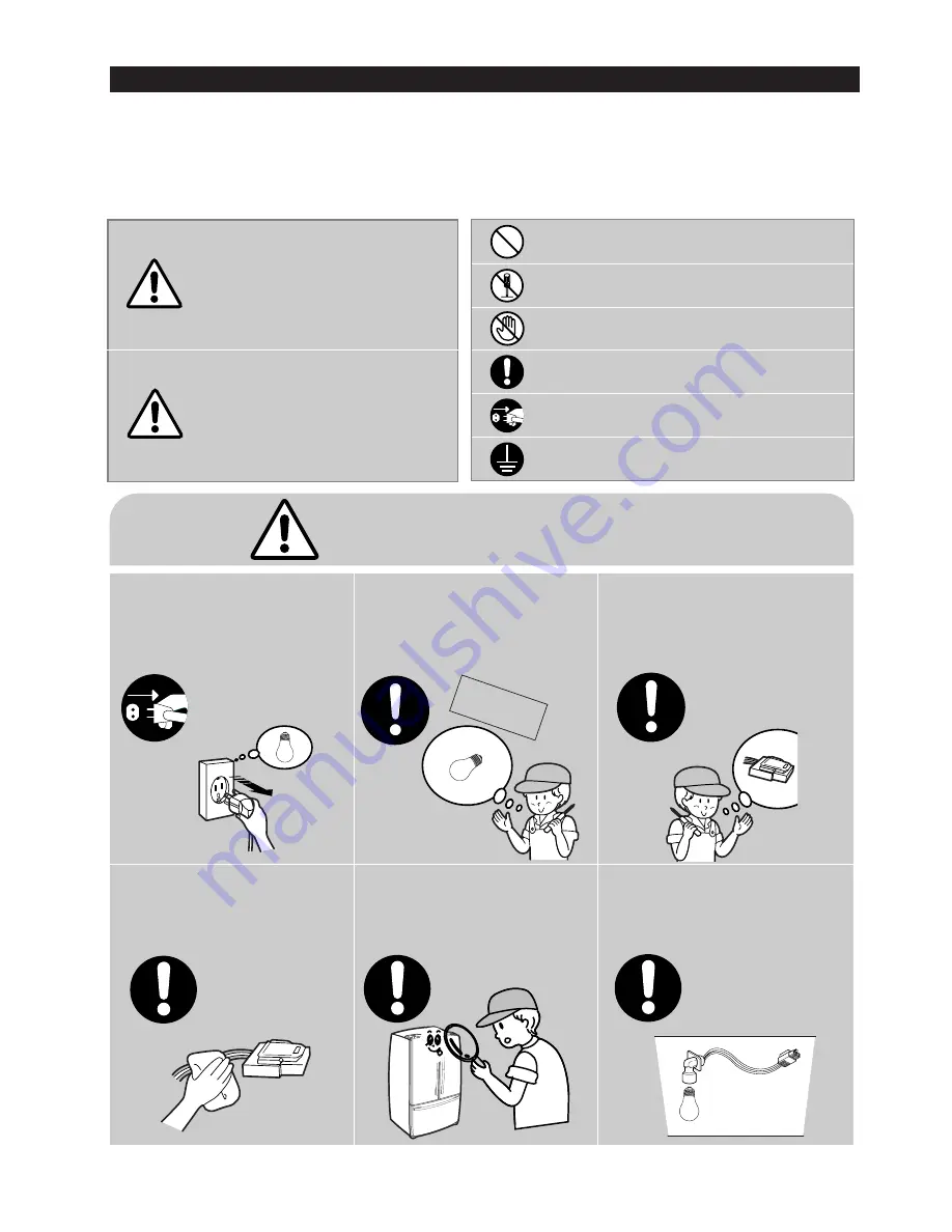
CAUTION/WARNING SYMBOLS DISPLAYED
SYMBOLS
Indicates that a
danger of death
or serious injury
exists.
Indicates that a risk
of personal injury
or material damage
exists.
means “Prohibited”.
means “Do not disassemble”.
means “No contact”.
means ”Warning or Caution”.
means “Earth or Ground”.
means “Unplug the unit before
preforming service”
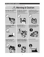
Plug out to exchange the interior
lamp.
●
It may cause electric shock.
Warning
Warning & Caution
Caution
Unplug
Use the rated components
on the replacement.
●
Check the correct model, rated
voltage, rated current, operating
temperature and so on.
On repair, make sure that the
wires such as harness are
bundled tightly.
●
Bundle tightly wires in order not to be
detached by the external force and then not
to be wetted.
Check if there is any trace
indicating the permeation
of water.
●
If there is that kind of trace, change
the related components or do the
necessary treatment
such as taping
using the
insulating tape.
After repair, check the
assembled state of components.
●
It must be in the same assembled state
when compared with the state before
disassembly.
On repair, remove completely dust
or other things of housing parts,
harness parts, and check parts.
●
Cleaning may prevent the possible fire by
tracking or short.
Rated
components
Summary of Contents for RFG297AABP
Page 21: ...20 PRODUCT SPECIFICATIONS 2 8 1 PRINCIPLE OF FREEZEER ...
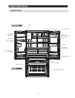
Page 26: ...25 Refrigerator PRODUCT SPECIFICATIONS 2 9 Cooling Air Circulation Freezer ...
Page 95: ...94 TROUBLESHOOTING SPMInternalDIODEVoltage ...
Page 97: ...96 TROUBLESHOOTING INVERTERPCBCircuitDiagram ...
Page 107: ...106 5 3 Connector Layout with part position Main Board PCB DIAGRAM 5 3 1 RFG29 AA ...
Page 108: ...107 5 4 Connector Layout with part position SMPS Board PCB DIAGRAM 5 4 1 RFG29 AA ...
Page 109: ...108 7 1 Model RFG295AA BETTER 7 WIRING DIAGRAM BLU BLU ...
Page 110: ...109 6 2 Model RFG297AA BEST 6 WIRING DIAGRAM 13V BLU BLU ...
Page 111: ...110 6 3 Model RFG299AA 7 LCD 6 WIRING DIAGRAM BLU BLU ...
Page 112: ...111 6 4 Model RFG294AA SEARS 6 WIRING DIAGRAM BLU BLU ...
Page 113: ...112 7 1 Whole block diagram 7 SCHEMATIC DIAGRAM 7 1 1 MODEL RFG295AA BETTER ...
Page 114: ...113 7 1 Whole block diagram 7 SCHEMATIC DIAGRAM 7 1 2 MODEL RFG297AA BEST ...
Page 115: ...114 7 1 Whole block diagram 7 SCHEMATIC DIAGRAM 7 1 3 MODEL RFG299AA 7 LCD ...
Page 116: ...115 7 1 Whole block diagram 7 SCHEMATIC DIAGRAM 7 1 4 MODEL RFG294AA SEARS ...
Page 118: ...117 7 2 CIRCUIT DIAGRAM SCHEMATIC DIAGRAM 7 2 1 Main ...
Page 119: ...118 7 2 CIRCUIT DIAGRAM SCHEMATIC DIAGRAM 7 2 2 INVERTER ...
Page 120: ...MEMO ...

