84
TROUBLESHOOTING
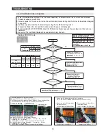
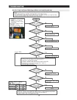
4-2-11. When refrigerator ROOM Lamp does not light up
1. When you replace the lamp of freezer, please power OFF to avoid an electric shock.
2. Please keep in mind you could get burnt by the excessive heating of an incandescent light bulb.
3. Bimetal is installed in the refrigerator LAMP. Check that if LAMP may be turned OFF by bimetal.
※
We only explaine about Fresh Food compartment in this page.
Because it is possible to repair the other room lamps with the same method.
1) AC LAMP
Start
Is the inside lamp
filament cut?
Is Lamp OFF by
bimetal operating?
Is the connection
point of R-door switch
normal?
Is the control relay
of the inside lamp in PCB
normal?(RY75)
Repair the inside lamp
Fresh food compartment
AC Lamp is applied only.
Repair door switch
Replace PCB and
Replace Relay
Check the connection of RDoor
switch and repair the inside lamp
socket
Reference
* The interior lamp relay operates lighting/lightout
according to door open / close.
* If interior lamp does not light, check the noise of relay
operation.
* Noise of relay operation sounds every Door Open /
Close.
* F-LAMP Relay -- RY74
* R-LAMP Relay -- RY75
Reference
If the door is opened, the contact of door switch will be opened and MICOM will get applied 5V to finally sense Open.
If 5V has been sensed over two minutes afterwards, Door-Open alarm will sound
‘
Ding-Dong
’
for 10 seconds in a oneminute cycle. For
that reason, if the door switch has failure, the refrigerator can make a
“
Ding-Dong
”
sound with oneminute cycle. Please note the step for
its service.
Wait for returning time
of bimetal
☞
When measure lamp resistance to the Wire
→
Resistance can be changed by Lamp input voltage.
(Actual measurement is below, it can be changed by
performance)
☞
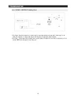
Checking method of Door Switch voltage
- Measuring voltage of CN30#2(Purple), CN30#1(black) and REG1, HEAT SINK
from PCB typical Ground part
→
See the R DOOR Switch at the following picture.
Wire color changed from
the following picture
☞
Fresh food
compartment lamp
CN70#9(Red)
↔
CN71#1 (Blue) ;
10Ohm
±
5%
Lamp ; 60W + 60W
☞
Freezer
compartment lamp
CN70#9(Red)
↔
CN71#3 (Gray) ;
15Ohm
±
5%
Lamp ; 60W
Typical PCB Ground REG1 Heater Sink
CLOSE
OPEN
Door & MICOM State
Door
F
MICOM
(#83)
Close
Open
5V(High)
0V(Low)
0V(Low)
5V(High)
R MICOM(#82)
Right and Left
Summary of Contents for RFG297AABP
Page 21: ...20 PRODUCT SPECIFICATIONS 2 8 1 PRINCIPLE OF FREEZEER ...
Page 26: ...25 Refrigerator PRODUCT SPECIFICATIONS 2 9 Cooling Air Circulation Freezer ...
Page 95: ...94 TROUBLESHOOTING SPMInternalDIODEVoltage ...
Page 97: ...96 TROUBLESHOOTING INVERTERPCBCircuitDiagram ...
Page 107: ...106 5 3 Connector Layout with part position Main Board PCB DIAGRAM 5 3 1 RFG29 AA ...
Page 108: ...107 5 4 Connector Layout with part position SMPS Board PCB DIAGRAM 5 4 1 RFG29 AA ...
Page 109: ...108 7 1 Model RFG295AA BETTER 7 WIRING DIAGRAM BLU BLU ...
Page 110: ...109 6 2 Model RFG297AA BEST 6 WIRING DIAGRAM 13V BLU BLU ...
Page 111: ...110 6 3 Model RFG299AA 7 LCD 6 WIRING DIAGRAM BLU BLU ...
Page 112: ...111 6 4 Model RFG294AA SEARS 6 WIRING DIAGRAM BLU BLU ...
Page 113: ...112 7 1 Whole block diagram 7 SCHEMATIC DIAGRAM 7 1 1 MODEL RFG295AA BETTER ...
Page 114: ...113 7 1 Whole block diagram 7 SCHEMATIC DIAGRAM 7 1 2 MODEL RFG297AA BEST ...
Page 115: ...114 7 1 Whole block diagram 7 SCHEMATIC DIAGRAM 7 1 3 MODEL RFG299AA 7 LCD ...
Page 116: ...115 7 1 Whole block diagram 7 SCHEMATIC DIAGRAM 7 1 4 MODEL RFG294AA SEARS ...
Page 118: ...117 7 2 CIRCUIT DIAGRAM SCHEMATIC DIAGRAM 7 2 1 Main ...
Page 119: ...118 7 2 CIRCUIT DIAGRAM SCHEMATIC DIAGRAM 7 2 2 INVERTER ...
Page 120: ...MEMO ...

