90
TROUBLESHOOTING
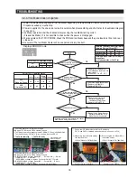
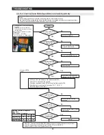
4-2-16. If Photosynthetic LED Lamp does not work properly
Sears model Option
* Please check the Power prior to repair, even though DC power does not cause electric shock.
This lamp operates related to COMP operation, please check the COMP first.
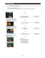
Remove the Photosynthetic LED lamp cover from the rear wall of Veg. Pan and connect battery to check the lamp operation.
1) C of 9V battery onto #1 and - of 9V battery onto #3. Check whether LED light up. When the battery contacting time is
longer, LED can be broken. Please contact it momentarily and just check the lighting.
- If LED doesn’t light up, you are recommended to replace the whole photosynthetic LED ASS’Y.
Start
Operate the COMP manually
and re-check
Is the COMP working?
No
MAIN PCB failure -
Replace
No
MAIN PCB failure - Replace IC75
failure
No
No
Normal Operation
[Option] Stop lighting when R
door opens.
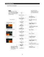
Remove the photosynthetic LED lamp cover and
follow to the Reference2 to check any failure.
Remove the photosynthetic LED lamp cover and
follow to the Reference2 to check any failure.
No
Yes
Yes
Yes
Yes
Yes
Does MAIN PCB IC75 #1 have
about 5V of input voltage?
Does MAIN PCB IC75 #18 have
about 0.7V of input voltage?
Does the Photosynthetic LED
lamp light up when the FF door
open?
Does the Photosynthetic LED
lamp work with the FF door
closed?
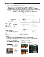
MICOM State
MICOM(#116) or IC75#1
Operate
5V (High)
Stand by
0V (Low)
IC75#1
Operate
0.7V (Low)
Stand by
11~13V (High)
Check by pressing the Door
Switch
Photosynthesis LED Lamp is
always on when the COMP
operates. Please operate the
COMP manually prior to check
the photosynthetic LED Lamp
Reference 2
Summary of Contents for RFG297AABP
Page 21: ...20 PRODUCT SPECIFICATIONS 2 8 1 PRINCIPLE OF FREEZEER ...
Page 26: ...25 Refrigerator PRODUCT SPECIFICATIONS 2 9 Cooling Air Circulation Freezer ...
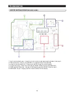
Page 95: ...94 TROUBLESHOOTING SPMInternalDIODEVoltage ...
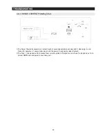
Page 97: ...96 TROUBLESHOOTING INVERTERPCBCircuitDiagram ...
Page 107: ...106 5 3 Connector Layout with part position Main Board PCB DIAGRAM 5 3 1 RFG29 AA ...
Page 108: ...107 5 4 Connector Layout with part position SMPS Board PCB DIAGRAM 5 4 1 RFG29 AA ...
Page 109: ...108 7 1 Model RFG295AA BETTER 7 WIRING DIAGRAM BLU BLU ...
Page 110: ...109 6 2 Model RFG297AA BEST 6 WIRING DIAGRAM 13V BLU BLU ...
Page 111: ...110 6 3 Model RFG299AA 7 LCD 6 WIRING DIAGRAM BLU BLU ...
Page 112: ...111 6 4 Model RFG294AA SEARS 6 WIRING DIAGRAM BLU BLU ...
Page 113: ...112 7 1 Whole block diagram 7 SCHEMATIC DIAGRAM 7 1 1 MODEL RFG295AA BETTER ...
Page 114: ...113 7 1 Whole block diagram 7 SCHEMATIC DIAGRAM 7 1 2 MODEL RFG297AA BEST ...
Page 115: ...114 7 1 Whole block diagram 7 SCHEMATIC DIAGRAM 7 1 3 MODEL RFG299AA 7 LCD ...
Page 116: ...115 7 1 Whole block diagram 7 SCHEMATIC DIAGRAM 7 1 4 MODEL RFG294AA SEARS ...
Page 118: ...117 7 2 CIRCUIT DIAGRAM SCHEMATIC DIAGRAM 7 2 1 Main ...
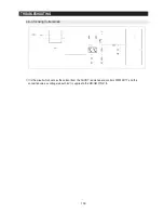
Page 119: ...118 7 2 CIRCUIT DIAGRAM SCHEMATIC DIAGRAM 7 2 2 INVERTER ...
Page 120: ...MEMO ...

