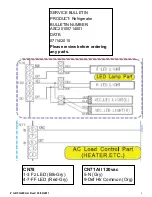
# tsRFG298AA RevC 03/30/2011
2
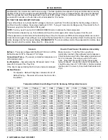
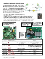
Temperature/Resistance/Voltage Chart for Samsung Refrigerators Sensors
Temp.
(Ω)
Volts Temp.
(Ω)
Volts Temp.
(Ω)
Volts Temp.
(Ω)
Volts
-29.2°F
64227 4.326
1.4°F
28021
3.685 32.0°F 13290 2.853 62.6°F
6771 2.019
-27.4°F
61012 4.296
3.2°F
26760
3.64
33.8°F 12749 2.802 64.4°F
6521 1.974
-25.6°F
57977 4.264
5.0°F
25562
3.594 35.6 °F 12233 2.751 66.2°F
6281 1.929
-23.8°F
55112 4.232
6.8°F
24425
3.548 37.4 °F 11741
2.7
68.0°F
6052 1.885
-22.0°F
52406 4.199
8.6°F
23345
3.501 39.2 °F 11271 2.649 69.8°F
5832 1.842
-20.2°F
49848 4.165
10.4°F
22320
3.453 41.0°F 10823 2.599 71.6°F
5621 1.799
-18.4°F
47431 4.129
12.2°F
21345
3.405 42.8°F 10395 2.548 75.2°F
5225 1.716
-16.6°F
45146 4.093
14.0°F
20418
3.356 44.6°F
9986
2.498 77.0°F
5000 1.675
-14.8°F
42984 4.056
15.8°F
19537
3.307 46.4°F
9596
2.449 78.8°F
4861 1.636
-13.0°F
40938 4.018
17.6°F
18698
3.258 48.2°F
9223
2.399 80.6°F
4690 1.596
-11.2°F
39002
3.98
19.4°F
17901
3.208 50.0°F
8867
2.35 86.0°F
4218 1.483
-9.4°F
37169
3.94
21.2°F
17142
3.158 51.8°F
8526
2.301 87.8°F
4072 1.447
-7.6°F
35433 3.899
23.0°F
16419
3.107 53.6°F
8200
2.253 89.6°F
3933 1.412
-5.8°F
33788 3.858
24.8°F
15731
3.057 55.4°F
7888
2.205 91.4°F
3799 1.377
-4.0°F
32230 3.816
26.6°F
15076
3.006 57.2°F
7590
2.158 95.0°F
3547 1.309
-2.2°F
30752 3.773
28.4°F
14452
2.955 59.0°F
7305
2.111 96.8°F
3428 1.277
-0.4°F
29350 3.729
30.2°F
13857
2.904 60.8°F
7032
2.064 100.4°F 3204 1.213
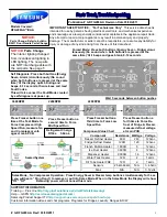
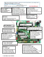
DC FAN MOTORS
Brushless DC Fan motors are used to save energy. The fans operate at two speeds. Fan speed information is read by
the Main PCB. If the fan speed exceeds 600 RPM or the speed is too slow, or stopped the fan drive circuit is disabled,
After 10 seconds the circuit tries again with 3 seconds of DC voltage. If the fan continues this activity for 5 cycles, 10
seconds off 3 seconds on, the fan drive circuit is disabled for 10 minutes.
TO TEST THE FAN CIRCUIT VOLTAGE.
Power off and back on to check the DC voltage to the motor, wait from 10 to 60 seconds for the fan voltage to kick in,
and then check fan voltage, the average reading is 9 VDC. If you get 3 seconds of voltage every 10 seconds for the 5
fan power up cycles, then the Main PCB is good.
NOTE:
You may need to put unit in FORCED FREEZE mode to activate the fans/compressor.
If the fan blade is blocked by ice, then defrost and check the motor again, after removing power from the unit.
If the evaporator is ice blocked and thus blocking the air flow, the fan will over RPM and it is stopped. Remove ice and
check the motor again. If everything is clear around the fan blade then the motor would be at fault. Continuous fan errors
will be displayed on the front panel display.
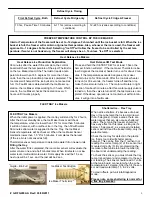
PLEASE NOTE:
The door switches control the evaporator fan motors. Have
them closed to test the motors. Delay time 10 – 60 seconds.
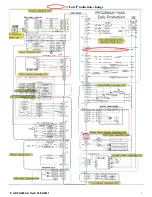
Sensors
Defrost
– The sensor voltage tells the Main PCB to turn off the
Defrost Heater At 50
o
in Freezer, 63
o
in Fridge
Compartment Temp
– The sensor controls fan/compressor on/
off to maintain temp
Ice Production
– harvests when the I/M sensor reads 1.5 de-
grees for 5 minutes, Flex Tray Only.
If the door is opened during that 5 minutes harvest is delayed.
Ambient Sensor
Fan Speeds – Below 60 degrees condenser fan is off
Defrost Timing – The warmer the room the more often
the defrost
How to Check Sensor Resistances Accurately
Make ice slurry. To do this, fill a cup with ice
(preferably crushed), then add water and a teaspoon
of salt to make a slush. Mix thoroughly and allow to sit
for 2 to 3 minutes. This will give you a 32*F refer-
ence. Now, lower the sensor into the mixture and
leave for about 1 minute, then check the resistance. It
should be very close to 13,300 ohms. Before reinstall-
ing the sensor, be sure to rinse it with fresh water and
dry it.


