# tsRFG298AA RevC 03/30/2011
8
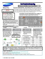
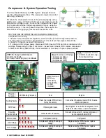
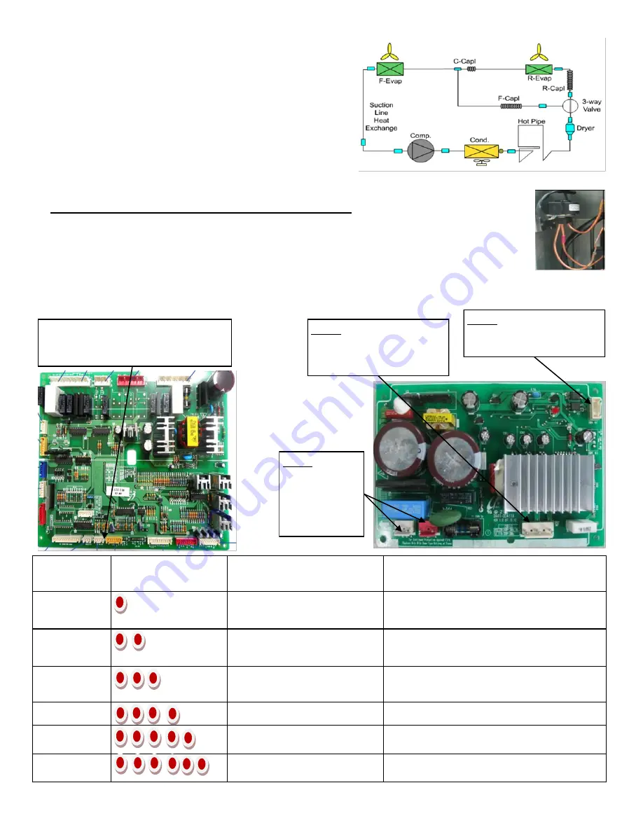
Compressor & System Operation Testing
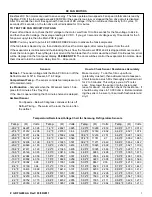
The Time Divided Multi-cycle (TDM) System (Stepper Valve) is
used to switch refrigerant flow . This improves temperature control
and energy efficiency.
If it fails in the all evaporator mode, it should work properly, using
slightly more energy. If it fails in the Freezer evaporator only mode,
there will be a Fridge no cool Force on the Fridge with the ―Power
Cool‖ option. Monitor the Fridge evaporator(s) temp by using the
Defrost Sensor(s). If the temp doesn’t decrease, then suspect the
Main PCB is not supplying signal to switch the diverter valve.
TEST BEFORE INTERPRETING LED BLINKING FREQUENCY
Compressor not running
1. Activate Forced Compressor Operation, wait 2 minutes (in case of high head pressure)
2. If compressor doesn’t start, check CN75 for 2~2.8vdc (if not there replace Main PCB)
3. Check for 120vac to inverter PCB CN02 L-N
4. If voltage is OK, remove power, disconnect CN03 (Inverter PCB) and check resistance to the
windings. Aproxametly10 ohms. If not correct , inspect wire harness, if OK replace compressor.
5. Disconnect CN02 (SMPS PCB), check resistance to Overload , if open replace overload.
CN04 Compressor Control
2- (CN40-4) 5vdc (Brn-Gry)
4 Comp Signal (Org)
CN03 Compressor Windings
1 Compressor (Blue)
3 Compressor (Prp)
5 Compressor (Wht)
CN02 Overload
& A/C Line
1 OLP (Brn)
3 OLP (S/Blu)
3 L (Blk)
1 N (Red)
CN75 To Comp Inverter Board
2-3 (Brn-Gry)
5vdc
4-3 Comp control (Org-Gry)
2~2.8vdc
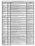
Protection
Functions
LED Blinking Frequency
Test
Replace
Starting Failure
Check the Inverter PCB & Comp
Relay Connectors
Connectors OK,replace Inverter PCB, if same,
replace compressor
SPM Fault
If blinking after reset,
Check System for restriction & refrigerant, if OK
replace Inverter, if same, replace compressor
Detecting
Position Failure
Check Inverter Connectors,
Connectors measure OK, replace compressor, if
same, replace Inverter PCB
Motor Locked
Compressor Locking
Compressor
Low Voltage
Compressor Locking, check input
voltage
Replace Inverter PCB, if same, replace
Compressor
Over Voltage
Compressor Locking, check input
voltage
Replace Inverter PCB, if same, replace
Compressor


