background image

36

AA

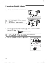
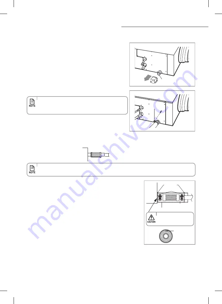
Drain pipe and drain installaton

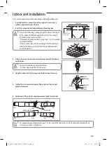
1.  Unscrew the 4 tapped screws to remove the cover of the drain hose 

connection port.

2.  Insert the flexible hose to the drain hose port.

Drain hose connection port

Cable clamp

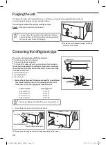
3.  Install the drain hose so that its length can be as short as possible. Internal diameter of the drain hose should be the 

same or slightly bigger than the external diameter of the drain hose port.

  

  Inner diameter of the drain hose

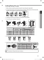
4.  Wrap the drain hose with the insulation drain as shown in figure and secure it.

32mm(Inner diameter)

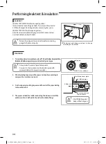
•  Install the drain hose with a slope away from the unit to give adequate drainage of condensate.
•   Fix the flexible hose to the PVC with the supplied cable tie securely.

•   Fix the flexible hose to the indoor unit wiht the supplied cable 

clamp securely.  

(Use the screwdriver to fix the flexible hose securely.)

Insulation drain hose

Insulation cover drain

Cable-tie

Clamp

No gap

•   Must fit tightly against 

body without any gap.

Indoor 

unit

RHF050KHEA_IB,IM_E_32885-3.indd   36

2011-10-12   오후 5:30:35

Summary of Contents for RHF050KHEA

Page 1: ...llation manual imagine the possibilities Thank you for purchasing this Samsung product To receive more complete service please register your product at www samsung com register I F S E P D DB98 32885A 3 RHF050KHEA_IB IM_E_32885 3 indd 53 2011 10 12 오후 5 30 42 ...

Page 2: ... is conducted to prevent condensation and air volume reduction How to use this unit This unit should be used with air conditioners Air conditioning is impossible only by this unit because this unit does not have temperature control function It s capacity is too small in order to control the room temperature to the whole And should be operated in combination with standard indoor units Interlocked o...

Page 3: ...urchase contract This product should not be mixed with other commercial wastes for disposal This product has been determined to be in compliance with the Low Voltage Directive 2006 95 EC and the Electromagnetic Compatibility Directive 2004 108 EEC of the European Union USINGPARTS Safety precautions 4 Checking before use 8 Checking the name of the parts 11 Basic operation 16 Cleaning and maintainin...

Page 4: ...ion is different it may cause fire The installation of this appliance must be performed by a qualified technician or service company Failing to do so may result in electric shock fire explosion problems with the product or injury Install a switch and circuit breaker dedicated to the product Failing to do so may result in electric shock or fire Fix the outdoor unit firmly so that the electric part ...

Page 5: ...objects or push the power line into the space behind the appliance This may result in electric shock or fire FORPOWERSUPPLY CAUTION When not using the product for a long period of time or during a thunder lightning storm cut the power at the circuit breaker Failing to do so may result in electric shock or fire FOR USING WARNING If the appliance is flooded please contact your nearest service center...

Page 6: ... fingers into the product Do not use the product as a ventilator for a burner If you use a burner with gas or gasoline you need to have separate ventilation system for the combustible apparatus If any foreign substance such as water has entered the appliance cut the power by unplugging the power plug and turning the circuit breaker off and then contact your nearest service center Failing to do so ...

Page 7: ...r plants This appliance is not intended for use by persons including children with reduced physical sensory or mental capabilities or lack of experience and knowledge unless they have been given supervision or instruction concerning use of the appliance by a person responsible for their safety Children should be supervised to ensure that they do not play with the appliance FOR CLEANING WARNING Do ...

Page 8: ...temperature is under 15 C the unit does not operate at all Do not operate the unit when typhoon comes Water may get in the room through the unit due to the rain and heavy winds Avoid operating the unit in indoor or outdoor with high temperature and humidity since dew may form on the internal part of the product including the heat exchanger Especially avoid using it during the long rainy period in ...

Page 9: ...oduct operates in Cool mode Protect compressor The product does not start operating immediately to protect the compressor of the outdoor unit after it has been started If the heat pump is operating in Heat mode De ice cycle is actuated to remove frost from an outdoor unit that may have deposited at low temperatures The internal fan is switched off automatically and restarted only after the de ice ...

Page 10: ...to control the room temperature to the whole and should be operated in combination with standard indoor units When a remote controller is only connected to the ERV with DX COIL independent operation is possible However temperature setting by remote controller is not possible In this ON OFF operation by thermostat depends on factory setting However this value is changeable by installation service m...

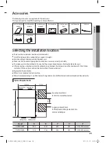
Page 11: ...ust Air Access for inspection maintenance A A Model A mm RHF050KHEA 450 x 450 RHF100KHEA 550 x 550 There is access for inspection maintenance for cleaning the air filter and the heat exchanger element Lack of installation and maintenance spaces may cause injury or malfunction There is also access for inspection maintenance of the DX coil and humidifier element RHF050KHEA_IB IM_E_32885 3 indd 11 20...

Page 12: ...ontroller user manual Wired remote controller not supplied Model MWR WE10 Display Checking the name of the parts Operation On Off button LED Indicator Green Normal Red Error Temperature Setting Button RHF050KHEA_IB IM_E_32885 3 indd 12 2011 10 12 오후 5 30 08 ...

Page 13: ...ys Scheduled device selection Displays Current time summer time scheduled time Ventilator ERV related information Displays Ventilator ERV operation Displays Clean up Displays Ventilator ERV fan speed Commom function related information Displays Invalid operation Filter cleaning filter cleaning period Displays Dust box cleaning alert check partial locking full locking Displays occupancy detection E...

Page 14: ...ts the desired unit operation Temperature setting button Sets the desired temperature Fan speed button Changes the unit fan speed Air Swing button Changes the air flow direction to move upward or downward Temp button Checks the indoor temperature Quiet Sleep button Selects Quiet or Sleep operation for the unit RHF050KHEA_IB IM_E_32885 3 indd 14 2011 10 12 오후 5 30 12 ...

Page 15: ...peed button Change the fan speed for your Ventilator ERV E Saver button Begin Energy Saving Operation Clean up button Select air purification through the in out load controls After cleaning the filter please press the FilterReset button The lamp will turn off and it will be turned on again upon the next cleaning period If you press a functional button not supported by the unit then the lamp will t...

Page 16: ... By Pass High Turbo Medium Auto High Turbo Medium After installing a CO2 sensor in your Ventilator ERV you can select from High Turbo Auto Medium Exception Quiet Operation Outing Operation Basic operations can be selected after pressing the Mode button WhenthewiredremotecontrollerisconnectedtoanERVwithDX COILandanAirconditionersimultaneously When controlling an ERV with DX COIL RHF050KHEA_IB IM_E_...

Page 17: ...e desired temperature Auto You can adjust the desired temperature by 1 C within a range of 18 C 30 C Cool You can adjust the desired temperature by 1 C within a range of 18 C 30 C Dry You can adjust the desired temperature by 1 C within a range of 18 C 30 C Fan You can t change the desired temperature Heat You can adjust the desired temperature by 1 C within a range of 16 C 30 C When controlling a...

Page 18: ...perate the cooling and heating operation of an ERV with DX COIL You cannot set the temperature by an ERV with DX COIL only You cannot select the dry operation if you operate an ERV with DX COIL only When you operate an ERV with DX COIL only cooling and heating operation is impossible When you operate an ERV with DX COIL and air conditioner at the same time the ERV with DX COIL follows the operatio...

Page 19: ...Detach the air filters by pulling them forward There are totally 4 air filters on both sides of the heat exchange element Change the air filters in every two years However changing frequency may vary according to the used period and condition If the air filter is damaged purchase it individually in a customer care center or an agency that you bought the product Make sure to turn off the power supp...

Page 20: ...e heat exchange element is heavy Take care not to drop it There are 2 heat exchange elements in the unit Make sure clean them at once If the heat exchange element is damaged purchase it individually in a customer care center or an agency that you bought the product Make sure to turn off the power supply Screw Heat exchange element Remove all dust and particles on the heat exchange elements with a ...

Page 21: ...o release any dirt Do not scrub the humidifier element Do not spray water directly onto the humidifier element with a hose Do not use detergent or water hotter than 40 C Reassemble the humidifier element and access panel Check whether the humidifier element is correctly assembled Otherwise this may result in water leakage and performance deterioration Remove 2 more screws Screw RHF050KHEA_IB IM_E_...

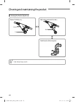
Page 22: ...product Cleaning the Strainer Optional Remove the Strainer cap Clean the mesh with running water Take out the mesh inside the strainer Strainer Cap Mesh Clean the mesh once a month RHF050KHEA_IB IM_E_32885 3 indd 22 2011 10 12 오후 5 30 28 ...

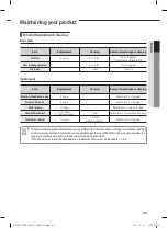
Page 23: ...ing 10 years Deterioration pipe water leak Humidifier element 7 10 years 1 000hours year 1 year Deterioration of saturation efficiency Feed water strainer 10 years 1 month Heating season Deterioration Clogging The product life and product durable years can be different from the table above according to installation condition and maintenance situation The table above is applicable when the use of E...

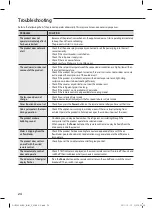
Page 24: ...peed does not change Check if you selected Quiet mode The product automatically adjusts the fan speed to Auto in Quiet mode Timer function does not set Check if you press the Power button on the remote control after you have set the time Odorspermeateintheroom during operation Check if the appliance is running in a smoky area or if there is a smell entering from outside Operate the product in Fan ...

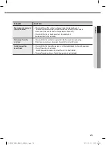
Page 25: ...t Remove all dust in the air intake Water drops from the air intake Check whether the ventilator is operated in By Pass mode during heating When heating make sure to operate the ventilator in Heat EX mode Humidity operation doesn t work Check whether the humidifier element is installed additionally for humidity operation Check if the unit is in heat mode Humidity operation works only when the unit...

Page 26: ...s if damaged If problems occur switch the unit off and disconnect it from the power supply In order to prevent electric shocks fires or injuries always stop the unit disable the protection switch and contact SAMSUNG s technical support if the unit produces smoke if the power cable is hot or damaged or if the unit is very noisy Always remember to inspect the unit electric connections refrigerant tu...

Page 27: ...e it is not observed as indicated into the Installation Manual the cost necessary to reach and repair the unit in safety as required by current regulations in force with slings trucks scaffolding or any other means of elevation won t be considered in warranty and charged to end user Hang down a blockage for bird in front of outdoor air suction duct If something such as bird s nest blocks the air s...

Page 28: ... in a climate of high temperature and humidity It may form dewdrop inside of the unit and heat exchange element Install Operation ranges Noise may increase when there are large amount of exhausting air Be sure to install the duct based on standard air volume When necessary control the air volume by installing volume damper If the noise continues install the noise chamber or flexible noise reducer ...

Page 29: ...d in this way that they are out of public access Not touchable by the users After connecting a chamber insulate the connection part between the indoor unit and the chamber with t10 or thicker insulation Otherwise there can be air leak or dew from the connection part Rigid wall without vibration Where it is not exposed to direct sunshine Where the replacement parts air filter heat exchange element ...

Page 30: ...763 340 84 160 362 170 Selecting the installation location 20mm or more 20mmormore A mm Spaceforinstallation B mm Model A B RHF050KHEA 320 600 RHF100KHEA 440 800 D C E F A B G G H H F I Unit mm No Name Description Liquid pipe connection ø6 35 1 4 Gas pipe connection ø12 70 1 2 Drain pipe connection VP25 OD ø32 ID ø25 Nominal diameter for duct RHF050KHEA ø200 RHF100KHEA ø250 RHF050KHEA_IB IM_E_3288...

Page 31: ...l theY joint before installing the indoor unit For proper drainage of condensate give 1 or less slant to the side of the unit which will be connected with the drain hose as shown in the figure Ensure that the ceiling is strong enough to support the weight of the indoor unit Before hanging the unit test the strength of each attached suspension bolt If the length of suspension bolt is more than 1 5m...

Page 32: ...the following torque Outer Diameter Torque kgf cm 6 35 mm 1 4 145 175 9 52 mm 3 8 333 407 12 70 mm 1 2 505 615 15 88 mm 5 8 630 769 2 Ensure there are no kinks or cracks on pipe bends There are two refrigerant pipes of differing diameters A smaller one for the liquid refrigerant A larger one for the gas refrigerant The inside of the copper pipe must be clean dry and free from debris The connection...

Page 33: ... 0 0 5 1 5 2 0 ø15 88 mm 0 0 5 0 0 5 1 5 2 0 4 Carry out flaring work using flaring as shown below Pipe Flare Flaring tool Clutch type Wing nut type A Die Copper pipe York Die Copper pipe Flare nut Indoor outlet pipe Connecting pipe Flare nut 5 Check if you flared the pipe correctly see examples of incorrectly flared pipes below 6 Align the pipes and tighten the flare nuts first manually and then ...

Page 34: ... Leak check 1 Toavoidcondensationproblems placeT13 0orthickerAcrylonitrile ButadienRubber separately around each refrigerant pipe 2 Wind insulating tape around the pipes and drain hose avoiding to compress the insulation too much 3 Finish wrapping insulating tape around the rest of the pipes leading to the outdoor unit 4 The pipes and electrical cables connecting the indoor unit with the outdoor u...

Page 35: ...use 1 grade thicker one according to the pipe size 25 19 5 Selecting the insulation for the refrigerant pipes Insulate the gas side and liquid side pipe referring to the thickness according to the pipe size The thickness according to the pipe size is a standard of the indoor temperature of 27 C and humidity of 80 If installing in an unfavorable conditions use thicker one Insulator s heat resistanc...

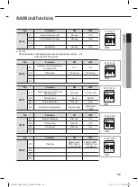
Page 36: ...r diameter of the drain hose 4 Wrap the drain hose with the insulation drain as shown in figure and secure it 32mm Innerdiameter Install the drain hose with a slope away from the unit to give adequate drainage of condensate Fix the flexible hose to the PVC with the supplied cable tie securely Fix the flexible hose to the indoor unit wiht the supplied cable clamp securely Use the screwdriver to fix...

Page 37: ...ainage Centralized Drainage 1 Install horizontal drainpipe with a slope of 1 100 or more and fix it by hanger space of 1 0 1 5m 2 Install U trap at the end of the drainpipe to prevent a nasty smell to reach the indoor unit Do not use the drain pump and allow the natural drainage Do not use the drain pump and allow the natural drainage 100mm or more Ceiling Horizontal drainpipe more than 1 100 slop...

Page 38: ... shown in figure 2 Confirm that the water flows out through the drain hose 3 Check drain water drops at the end of the drain pipe 4 Check that no water leaks from joints in the drain installation 5 Reassemble the cover of water supply intake The use of flexible hose made of fiber glass is recommended to minimize noise Install the duct at least over 3m to reduce the noise as well If the duct is not...

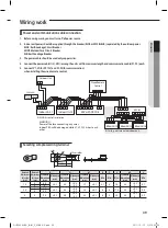
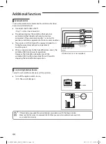
Page 39: ...al dimensions forcable mm2 Norminal dimensions forscrew mm B D d1 E F L d2 t Standard dimension mm Allowance mm Standard dimension mm Allowance mm Standard dimension mm Allowance mm Min Min Max Standard dimension mm Allowance mm Min 1 5 4 6 6 0 2 3 4 0 3 0 2 1 7 0 2 4 1 6 16 4 3 0 2 0 0 7 4 8 2 5 4 6 6 0 2 4 2 0 3 0 2 2 3 0 2 6 6 17 5 4 3 0 2 0 0 8 4 8 5 4 4 9 5 0 2 5 6 0 3 0 2 3 4 0 2 6 5 20 4 3 ...

Page 40: ...indoor units Apply following equation Installing with one size cable Installing with two size cables h Calculation The capacity of ELCB or MCCB ELB X A 1 25 X 1 1 X Ai T coef 1 55 T Lk Distance among each indoor unit m Ak Power cable specification mm2 ik Running current of each unit A Coef 35 6 Lk ik 10 of input voltage V 1000 Ak n k 1 Example of Installation Total power cable length L 100 m Runni...

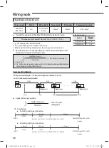
Page 41: ...nnection from the power supply must be incorporated in the fixed wiring 3mm You must keep the cable in a protection tube Keep distances of 50mm or more between power cable and communication cable Maximum length of power cables are decided within 10 of power drop If it exceeds you must consider another power supplying method The circuit breaker ELCB or MCCB ELB should be considered more capacity if...

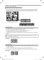
Page 42: ...refore you must set it to operate the product properly You can set the MAIN address from 00 to 99 by mixing SW01 and SW02 The MAIN address from 00 to 99 should differ from each other Check the indoor unit address on the plan that you are to install and set the address according to the plan Setting RMC Address The SW03 SW04 RMC switch is the address setting switch for controlling the indoor unit wi...

Page 43: ...N OFF SW07 K9 Indoor Expansion Valve For Heating Stop 160 step 35 160 step K10 Master Slave Slave Master K11 External control Not use Use K12 External control output Thermo Check Operartion Check No Function ON OFF SW08 K13 External damper Not use Use K14 S Plasma ion Not use Use K15 CO2 sensor Not use Use K16 No Function ON OFF SW09 K17 Clean up Exhaustion air RPM is fixed as Quiet mode RPM Suppl...

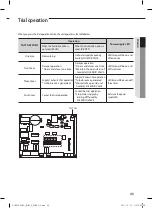
Page 44: ...ted in the last used condition If you enter a kitchen hood the supply air operates in Turbo fan speed and exhaust air operates in Low fan speed When a signal comes to the humidification sensor the ventilator ERV continues its operation However the humidity solenoid valve of the ventilator ERV will be closed and this will result in stopping the humidification operation Turn off the option switch to...

Page 45: ...closes one time Damper operation Opens and closes one time Maintain the open status of humidity SOLENOID VALVE LED lamp will be on and off two times Three times Supply Exhaust FAN operation Turbo breeze is generated Supply Exhaust Fan operation Turbo breeze is generated Maintain the open status of humidity SOLENOIDVALVE LED lamp will be on and off three times Four times Cancel the trial operation ...

Page 46: ...etect a gas leak Electric wiring connections Heat resistant insulation of the pipe Drainage Earth conductor connection Correct operation follow the steps below Insulation 1 How to start and stop the product 2 How to select the modes and functions 3 How to adjust the temperature and fan speed 4 How to adjust the airflow direction 5 How to set the timers 6 How to clean and replace the filters When y...

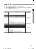
Page 47: ...pen short E123 EVA OUT Sensor open short E128 Breakaway of EVA IN Sensor E129 Breakaway of EVA OUT Sensor E174 EVA INAir sensor open short E151 Error of EEV open E152 Error of EEV close E161 Error of mixed operation E201 Communication error from outdoor unit due to the mismatching of the communication numbers and installed numbers after tracking E121 IndoorTemperature Sensor open short Errors rela...

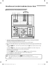
Page 48: ...nter the sub menu setting screen Using the buttons select a sub menu number and press the button to enter data setting screen When you enter the setting stage the current setting will be displayed Refer to the chart for data settings Using the buttons select the settings Press the button to move to the next setting Press the Set button to save the settings and exit to the sub menu setting screen P...

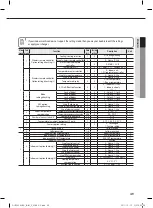
Page 49: ... Nouse 1 Use 5 RoomTemperature compensation Temperaturecontrolreference 1 2 3 0 9 40 C 0 1 C Temperaturecompensationvalue 4 5 6 0 9 9 9 9 C 0 1 C 6 Numberofconnectedunits Numberofindoorunits 1 2 0 16 NumberofERVs 3 4 0 16 7 Temperatureincrement decrement Conly 1 0 0 1 C 1 0 5 C 2 0 1 C 0 Factoryoptionsetting 1 0 0 Unchanged 1 Factorysetting 2 1 Softwarecode 1 6 Softwarecode 2 Softwareversion 1 6 S...

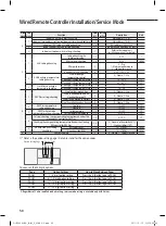
Page 50: ...st 3 0 Nouse 1 Use UseofhumidificationwhenHeating 4 0 Nouse 1 Use 2 ERVPlustemperature setting checking Cooling 1 2 15 30 C 1 C Heating 3 4 15 30 C 1 C 3 ERVPlusAutomode temperaturesetting checking Settemperature 1 2 15 30 C 1 C Settemperaturedifference 3 4 5 15 C 1 C 4 Setting checkingthecompensatingtemperatureAunderthe HeatingEEVcontrolforERVPlus 1 2 0 10 C 1 C Checkingthecompensatingtemperature...

Page 51: ...Data1 Press button to select no 1 The wired remote controller option is changed from Nonuse of cold breeze prevention to Use of cold breeze prevention 5 Press Set button to complete the option setting Save the setting value and exit to sub menu 6 Press Esc button to exit to normal mode 1 2 3 4 Data bit Data1 Nonuse of cold breeze prevention Data2 Cold breeze prevention Non use of humidification wh...

Page 52: ...g com KOSOVO 381 0113216899 www samsung com LUXEMBURG 261 03 710 www samsung com MACEDONIA 023 207 777 www samsung com MONTENEGRO 020 405 888 www samsung com NETHERLANDS 0900 SAMSUNG 0900 7267864 0 10 Min www samsung com NORWAY 815 56 480 www samsung com POLAND 0 801 1SAMSUNG 172 678 48 22 607 93 33 www samsung com PORTUGAL 808 20 SAMSUNG 808 20 7267 www samsung com ROMANIA 08010 SAMSUNG 08010 726...

Reviews: