74
5. PCB DIAGRAM
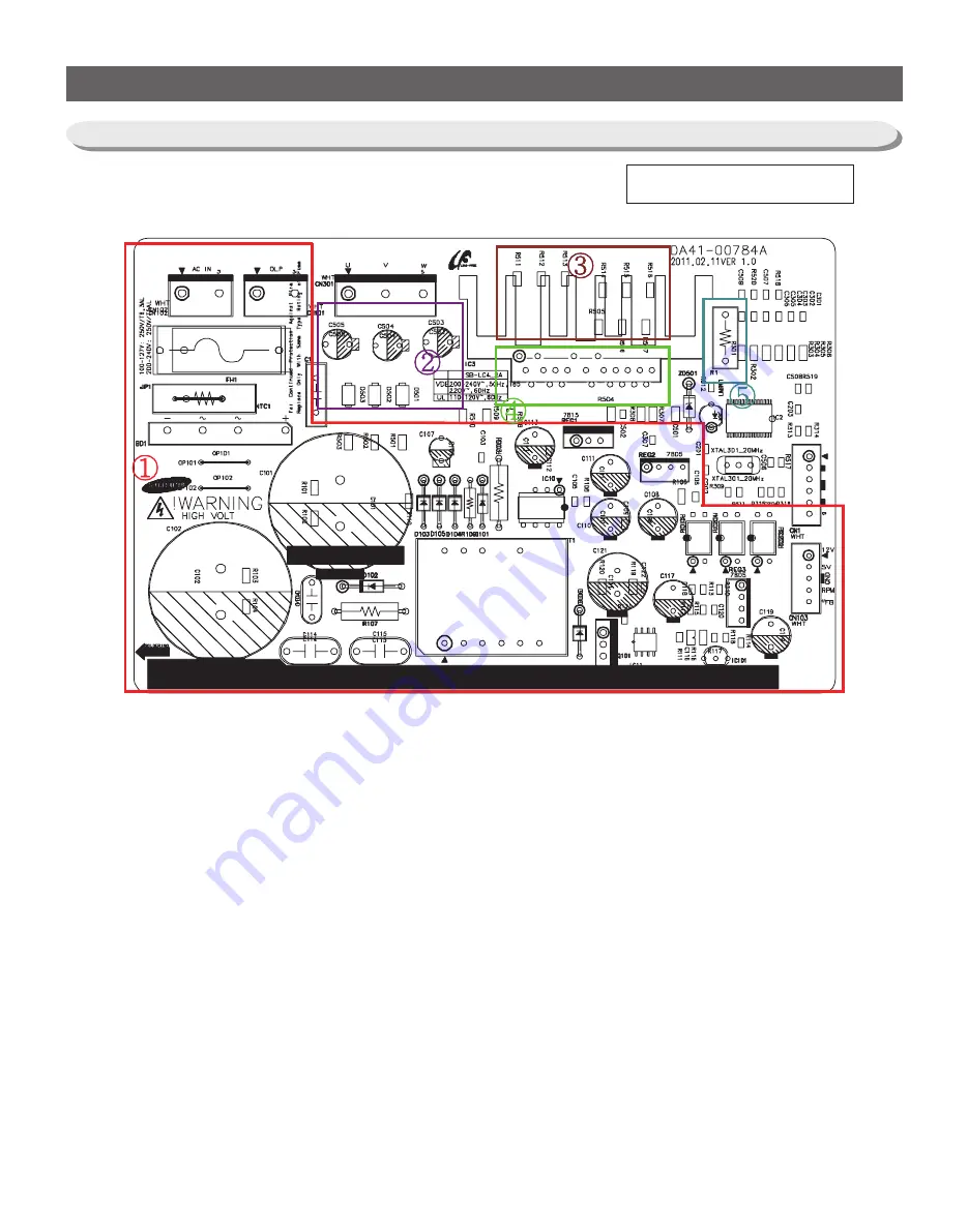
1. PCB Power Supply : Circuit changing the input power to the fridge control power with SMPS.
After converting to 12V and 5V, supply them to Main PBA.
After converting to 15V and 5V, use them for Inverter control.
2. Bootstrap Circuit : Independent Power Circuit for IPM High-Phase Driving.
3. Location Pick-Up Circuit : Detection of Rotor Location by monitoring the U/V/W-Phase of Compressor.
4. IPM : It is a Power Module which consists of HVIC(1), LVIC(1), IGBT(6) and Diode(6) and drives the
compressor with IGBT On/Off controlling at the Micom.
5. Shunt Resistor : Compressor Current Detection Circuit. It protects the compressor from over-currents by
monitoring the voltage applied to the related resistance.
5-2) Parts Layout (Inverter Board)
Q/J-OPTION
Summary of Contents for RL60GG Series
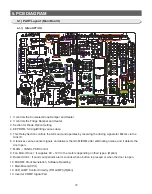
Page 75: ...75 5 PCB DIAGRAM 5 3 Connector Layout and Description Main Board 5 3 1 Q G J OPTION...
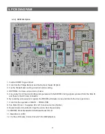
Page 76: ...76 5 PCB DIAGRAM 5 3 2 R P Z H Option...
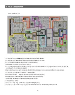
Page 77: ...77 5 PCB DIAGRAM 5 3 3 L Option...
Page 78: ...78 5 PCB DIAGRAM 5 3 4 W E Option...
Page 80: ...80 5 PCB DIAGRAM IPM DIODE VOLTAGE 5 5 IPM Diode Voltage...
Page 81: ...81 6 WIRING DIAGRAM 6 1 Q G J OPTION...
Page 82: ...82 6 WIRING DIAGRAM 6 2 R P Z H Option...
Page 83: ...83 6 WIRING DIAGRAM 6 3 L Option...
Page 84: ...84 6 WIRING DIAGRAM 6 4 W E Option...
Page 85: ...85 6 WIRING DIAGRAM 6 5 S Option...
Page 86: ...86 7 CIRCUIT DIAGRAM 7 1 Schematic Diagram PBA Main 7 1 1 Q G J OPTION...
Page 87: ...87 7 CIRCUIT DIAGRAM 7 1 2 R P Z H L Option...
Page 88: ...88 7 CIRCUIT DIAGRAM 7 1 3 W E S Option...
Page 89: ...89 7 CIRCUIT DIAGRAM 7 2 Schematic Diagram PBA Inverter...
Page 90: ...90 7 CIRCUIT DIAGRAM 7 3 Block Diagram PBA Main...
Page 91: ...91 7 CIRCUIT DIAGRAM 7 4 Block Diagram PBA Inverter G H L P R Z Option...
Page 92: ...92 7 CIRCUIT DIAGRAM 7 5 Block Diagram PBA Inverter Q J Option...


