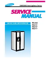
background image

RS2*3*

RS2*2*

RS2*1*

Model:

SIDE-BY-SIDE REFRIGERATOR

SAMSUNG Home Appliance Service

Summary of Contents for RS2 series

Page 1: ...RS2 3 RS2 2 RS2 1 Model SIDE BY SIDE REFRIGERATOR SAMSUNG Home Appliance Service ...

Page 2: ...e may result in personal injury and property damage The manufacturer or dealer cannot be responsible for the interpretation of this information SAMSUNG ELECTRONICS AMERICA INC Technical Service Guide Copyright ⓒ2004 All rights reserved This service guide may not be reproduced in whole or in part in any form without written permission from the SAMSUNG ELECTRONICS Company WARNING ...

Page 3: ...struction on services 4 2 Warranty information 9 3 Mechanical Disassembly 14 4 Circuit Diagram 15 5 Operation Principles By Parts Of Circuit 16 6 Illustrated Parts Catalog 26 Appendix Ⅰ Ⅰ Reference for circuit diagnostics 31 ...

Page 4: ...mbled state when compared with the state before disassembly Check the surrounding conditions of the installed refrigerator When the refrigerator is located at humid or wet place or the installed state is unstable change the location If needed do the ground Especially if there is a possibility of the electric leakage this appliance must be properly grounded Do not allow consumers to use one outlet ...

Page 5: ...uses for which this product was not intended altered product or serial numbers cosmetic damage or exterior finish accidents abuse neglect fire water lightning or other acts of nature use of products equipment systems utilities services parts supplies accessories applications installations repairs external plumbing and leaks external wiring circuit breakers fuses or connectors not supplied and auth...

Page 6: ...ilter 8 Damper in the Refrigerator 9 Twin cool in the Refrigerator 9 Refrigerator Thermistor 9 Door Bin in Freezer 10 Freezer Door Light Switch 10 Plastic Wire Drawer in Freezer 10 Freezer Shelf 10 Ice Dispenser Ice Maker 10 Auger Motor Case 11 Freezer Light 12 Evaporator Cover in Freezer 12 Evaporator Fan Motor 12 Evaporator in Freezer 13 Freezer Thermistor 13 Ambient Thermistor 13 Ice Maker Ther...

Page 7: ...d motion until it disengages the locking tabs Pull the handle outward to remove it The door gasket is a molded gasket set into a channel located in the door liner 1 Open the door 2 Grasp the gasket and pull in an outward motion until the molded gasket separates from the door liner The refrigerator has a door light switch located in the upper right corner for the refrigerator 1 Use a small flat bla...

Page 8: ...t goes 2 Tilt the drawer up and pull it out until it is removed The door bins allow storage of perishable items 1 Push the bin up and slide it out The water filter is located in the bottom left hand corner of the refrigerator The water filter filters water for the ice maker and the water dispenser 1 Turn the water filter 1 2 turn counterclockwise and pull it down 2 To install the filter align the ...

Page 9: ...over down 3 Remove the screw at the cover damper 4 Take off sensor and lamp wire connector located on the upper liner 6 Remove the damper from the refrigerator 1 Pull out the Twin cool by unlocking the hooks The refrigerator thermistor is located inside of the upper light cover of the refrigerator Twin cool in the Refrigerator Refrigerator Thermistor THERMISTOR ...

Page 10: ...connector and remove the switch Drawers are designed for storage of meat and dry foods The drawers are located in the lower portion of the freezer 1 Pull out the drawer as far as it goes 2 Tilt the drawer up and pull it out until it is removed The shelves slide out for easy access for frozen items 1 Slide the shelf out until it reaches its stop 2 Tilt down and slide it out of thecompartment Door B...

Page 11: ...t of ice tray 2 Lift the front locking tab and assemble the ice maker kit 3 Connect the ice maker wire connector 4 Match the tab holes and tabs 2 located on the top of the liner and slide the ice maker in 5 Tighten the screws 2 of the ice maker support This shelf is designed to support the ice maker ice dispensed and Xtra SpaceTM 1 Remove the Xtra SpaceTM cover to push it down and pull front 2 Sli...

Page 12: ... than remove fan and protector motor 2 Remove screw located at the four corners of the fan bracket 3 Take the fan motor assembly off 1 Remove screw 6 2 Remove the assy cover multi fre 3 Remove the assy cover supt motor fre 4 Remove screw 2 5 Remove the cover evap front 6 Disconnect the sensor wire connector Evaporator Fan Motor Freezer Light Evaporator Cover in Freezer Mechanical Disassembly ASSY ...

Page 13: ...and outlet tubes 4 Remove the evaporator 5 Take the same steps to seal the system as mentioned earlier The freezer thermistor is located at the top left of freezer vent It sends temperature signals to the micro processor The Ice Maker thermistor is located in its bottom The temperature signal sends the micro processor Evaporator in Freezer Mechanical Disassembly Freezer Thermistor Ice MakerThermis...

Page 14: ...binet 2 Take the solenoids assembly out 3 Disconnect water tubes The condenser Fan is located in the middle of machine compartment It cools down the sub condenser and the compressor 1 Lift up the rib under the support motor 2 Pull the support motor The condenser is located in the machine compartment The heat is extracted by condenser fan 1 Desolder the compressor discharge the condenser outlet 2 T...

Page 15: ...15 4 CIRCUIT DIAGRAM ...

Page 16: ...s through the diode D101 and D104 is changed to DC and provide constant 12V It provides 5V to MICOM and other circuits via regulator REG102 MC7805ACT and make entire PCB operate It is an Oscillation Circuit for synchronism clock generation and time calculation on the information sending receiving of the MICOM internal logic elements and when specifications for Resonator change the timing system of...

Page 17: ...failure Upon the power supply the reset terminal voltage becomes LOW for several tens of compared to Vcc voltage DC 5V at MICOM and it maintains HIGH Vcc Voltage during normal operation But when Vcc drops down to 3 4 3 7V the reset terminal voltage becomes LOW A semiconductor memory EEPROM stores data remembering previous settings regardless of power off which are indispensable especially in power...

Page 18: ...des 5 volt which is recognized as door is opened and turn off the fan at different load When the door is closed the voltage goes out from R402 to Switch the MICOM is applied with OV and the door is recognized as closed 3 Q401 is the circuit to turn off the auger motor operation when the door is opened If the door is closed Vcc voltage of R402 works as ground via door switch OV is applied to the ba...

Page 19: ...n and vice versa R302 4 6 9 and C301 C303 C305 are parts for noise prevention but they are not related to temp sensing characteristics 2 If Vf is the incoming voltage to MICOM in case of F Sensor Vf equals Rth Vcc R301 Rth Where Rth is resistance of THERMISTOR corresponding to Temp Please refer to the Appendix Temp to Sensor Resistance Voltage conversion table Temp to MICOM Terminal Voltage includ...

Page 20: ...67 8526 Voltage V 3 773 3 729 3 685 3 64 3 594 3 548 3 501 3 453 3 405 3 356 3 307 3 258 3 208 3 158 3 107 3 057 3 006 2 955 2 904 2 853 2 802 2 751 2 7 2 649 2 599 2 548 2 498 2 449 2 399 2 35 2 301 Temp 12 F 11 1 C 13 F 10 6 C 14 F 10 0 C 15 F 9 4 C 16 F 8 9 C 17 F 8 3 C 18 F 7 8 C 19 F 7 2 C 20 F 6 7 C 21 F 6 1 C 22 F 5 6 C 23 F 5 0 C 24 F 4 4 C 25 F 3 9 C 26 F 3 3 C 27 F 2 8 C 28 F 2 2 C 29 F ...

Page 21: ...on to make the damper open or close 3 Since the damper always touches the cold air DC 12V 1W heater is installed always on to prevent the malfunction from moisture and is controlled on conditions Operation conditions can be changed Micon 15 pin connected to IC4 controls the damper heater like category 3 1 KEY SCAN When Grid 6 is output this signal goes through PCB resistance 10 and provided to pow...

Page 22: ...al via input terminal of IC5 KID65783AP or TD62783AP Output wave always goes through LED input terminal with DC11 12V on every period At this time if SINK signal comes out at IC4 DC11 12V is applied to LED input terminal and output terminal sinks to OV which turn on LED for 2ms For example to turn on Power Fre LED IC4 16 pin sinks to 0V when IC5 16 becomes DC 11 12V making Power Fre LED turn on GR...

Page 23: ... pin 15 of IC3 via coil and goes into the ground While current flows to the coil the magnetic power arise it turns on the secondary contact point inside of RY75 and operates when the AC power is supplied to the both side of comp When MICOM 29 Pin becomes Low 0V IC3 4 Pin becomes Low which makes Power cut and current of RY75 RELAY cut So secondary contact becomes off due to magnetic field cut which...

Page 24: ...d in common 11 output port of IC4 gets on and the current flows into Ground making motor rotates This motor rotates the gear and rotates the ejection tray The tray twists to separate the ice from the tray and return to the horizontal state 3 For restoration motor stops for 2 seconds when the ejection is completed and to rotate in opposite direction output horizontal MICOM port with high and perfor...

Page 25: ...on and turned on after the modification Refer to the table below the default factory values are highly recommended unless exceptional cases OP11 OP12 OP11 OP12 MODEL RS2 11 RS2 21 RS2 31 FUNTION No Cruch 3 Step Light Cruch 3 Step Light Cruch 5 Step P F L T Lock Filter Indicator D601 D602 Fill Time 5 Sec 6 Sec 7 Sec 10 Sec Remark Flow Sensor Not USE Jumper USE OP2 Water Fill Time Control Option Dio...

Page 26: ...5 14 6 14 7 14 2 11 5 11 4 12 5 15 2 15 3 15 4 15 1 15 6 15 7 15 8 15 5 12 4 12 3 11 3 11 1 12 1 11 2 12 2 1 1 1 2 1 5 1 6 1 4 1 10 1 12 1 20 1 19 17 2 2 2 2 1 2 8 2 5 2 9 2 10 2 11 2 13 2 16 2 14 2 17 2 18 2 15 2 12 2 6 2 7 3 2 3 2 4 1 18 1 16 4 13 4 1 4 2 4 3 4 4 4 5 1 17 1 14 1 15 1 3 1 8 1 7 1 9 1 11 1 13 1 22 1 21 18 ...

Page 27: ...27 Illustrated Parts Catalog 6 2 Refrigerator 1 8 17 13 14 15 11 12 9 10 8 1 8 3 8 4 8 5 8 7 8 2 8 6 2 2 1 2 2 3 4 5 6 7 16 3 2 4 2 3 1 4 1 11 1 11 2 12 1 12 2 6 1 7 1 6 3 7 3 6 2 7 2 ...

Page 28: ...t 5 9 6 4 7 8 35 10 11 12 13 14 15 32 31 33 30 28 26 27 27 1 27 2 27 3 27 6 27 4 27 5 29 25 24 16 34 17 18 19 20 21 22 23 14 1 14 2 14 3 26 1 26 2 26 3 14 1 1 14 1 2 14 1 3 14 1 4 14 2 1 14 2 3 14 2 4 14 2 5 14 2 6 14 2 2 3 2 24 1 24 3 24 2 ...

Page 29: ...29 Illustrated Parts Catalog 6 4 DisassemblyofFreezeDoor 14 1 9 11 8 7 6 2 3 4 15 12 5 13 14 3 14 1 9 2 9 3 9 1 10 8 1 8 2 8 3 8 4 8 5 8 6 9 9 9 4 9 10 9 11 9 5 9 6 9 7 9 8 14 2 ...

Page 30: ...30 Illustrated Parts Catalog 6 5 Disassemblyof RefrigeratorDoor 2 1 12 11 2 4 10 13 5 6 7 9 8 12 3 12 1 12 2 ...

Page 31: ...GSLIPPEDAWAY COIL WIRESHORT COIL WIRECUT COIL WIRESHORT COIL WIRECUT COIL WIRESHORT COIL WIRECUT COIL WIRESHORT COIL WIRECUT MOTOR WIRESHORTMOTOR WIRECUTOR HOUSINGSLIPPEDAWAY MOTOR WIRESHORT MOTOR WIRECUTORHOUSINGSLIPPEDAWAY WATER VALVE ICE MAKER CN70 CN71 0Ω Ω WATER VALVE DISPENSER CN70 CN71 0Ω Ω AUGER MOTOR CN70 CN71 0Ω Ω CUBE SOLENOID CN70 CN71 0Ω Ω COMP FAN MOTOR CN71 0Ω Ω F FANMOTOR CN71 0Ω Ω...

Page 32: ...ACTOPEN FAULTYDRIVINGCIRCUIT RY74NOCONTACTOPEN FAULTYDRIVINGCIRCUIT RY79NOCONTACTOPEN FAULTYDRIVINGCIRCUIT RY77NOCONTACTOPEN FAULTYDRIVINGCIRCUIT RY71NOCONTACTOPEN FAULTYDRIVINGCIRCUIT RY72NOCONTACTOPEN FAULTYDRIVINGCIRCUIT Turn on Power and check status of Relay Driving Circuit by checking followings according to load operation Check after disassembling connected to MAIN PCB CN30 CN32 Because it ...

Page 33: ... FAX 82 62 950 6829 ELECTRONICS Samsung Electronics Co Ltd Refrigerator Division 2004 2 Printed in Korea Code DA82 00 This Service Manual is a property of Samsung Electronics Co Ltd Any unauthorized use of Manual can be punished under applicable International and or domestic law ...

Reviews: