

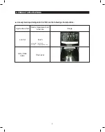


RS261M**, RS26DD**
SIDE BY SIDE
MODEL NAME : RS261M**
RS26DD**
REFRIGERATOR
REFRIGERATOR
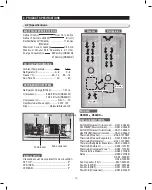
CONTENTS
For the latest information, please access our service web site (http://itself.sec.samsung.co.kr)
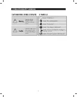
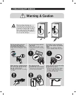
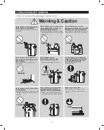
1. PRecautionS(SaFety WaRningS)
···············
4
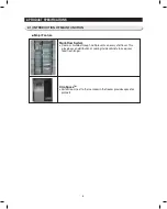
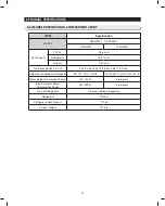
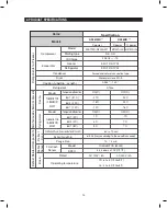
2. PRoDuct SPeciFicationS
······································
7
3. DiSaSSeMbly anD ReaSSeMbly
················
19
4. tRoubleShooting
···················································
34
5 . exPloDeD VieW & PaRtS liSt
······················
57
6. WiRing DiagRaM
···························································
74
7. Pcb DiagRaM
·····································································
75
8. ScheMatic DiagRaM
·················································
77
9. ReFeRence inFoRMation
···································
79
Summary of Contents for RS261M Series
Page 76: ...74 6 WIRING DIAGRAM ...
Page 78: ...76 7 PCB DIAGRAM 7 2 CONNECTOR ARRANGEMENT Main Board RS261MD RS26DD XAP RS26DD SAM ...
Page 79: ...77 8 SCHEMATIC DIAGRAM 8 1 Block Diagram ...
Page 80: ...78 8 SCHEMATIC DIAGRAM 8 2 Schematic Diagram ...
Page 82: ...80 9 REFERENCE INFORMATION 9 1 1 model name nomenclature 9 1 model name nomenclature q a ...


