


75
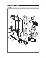
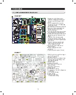
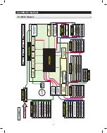
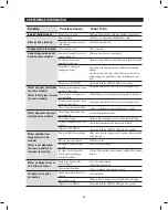
7-1) PART ARRANGEMENT (Main Board)
7. PCB DIAGRAM
1. ac power on the Pcb power part
(SMPS)ais supplied and converted to
Dc12V, 5V and gnD through SMPS
circuits.
2. Power is supplied to the fan motor
driving part up to 8.3V~10V depending
on the type of motor.
3. eePRoM:Saves or records various data.
4. Receives various sensor signals and
removes noise with MicoM and
transfers them again.
5. Plays role of operating the genuine room
taste damper and the damper heater.
6. Displays leD to the genuine room taste
display driving part,and processes key
signals.
7. D isplays leD to the panel display
driving part,and processes key signals.
(controlled in the link with genuine room
taste circuits)
8. Performs i ce-maker operati on and
suppl i es power of the motor and
senses change of switches.
9. Relay part to control Relay part to
control ac load.
10. option setting part for model
separation.
11. connector part to connect ac load.
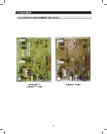
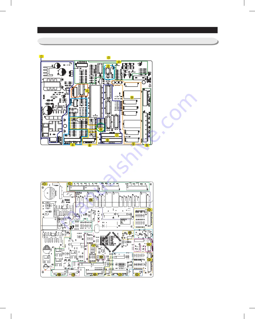
RS261MD**
RS26DD***
1. SMPS circuit : With input ac voltage, it
outs 12 VDc and 5 VDc.
2. ac load connector.
3. Receives various sensor voltages, door
operation signals. after filtering, send
each signal to MicoM.
4. Damper control.
5. Dispenser S/W control.
6. Plc circuit.( Plc : Power line
communication)
7. leD-Room-lamp control.
8. Display control.
9. ice MakeR kit control.
10. it supplies 8.3~10.3VDc to Deodorizer
& Fan Motor.
11. ac comp control relay.
12. Micom Writing.
13. eePRoM : Data store.
a.Diode option setting.
Summary of Contents for RS261M Series
Page 76: ...74 6 WIRING DIAGRAM ...
Page 78: ...76 7 PCB DIAGRAM 7 2 CONNECTOR ARRANGEMENT Main Board RS261MD RS26DD XAP RS26DD SAM ...
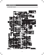
Page 79: ...77 8 SCHEMATIC DIAGRAM 8 1 Block Diagram ...
Page 80: ...78 8 SCHEMATIC DIAGRAM 8 2 Schematic Diagram ...
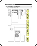
Page 82: ...80 9 REFERENCE INFORMATION 9 1 1 model name nomenclature 9 1 model name nomenclature q a ...


