62
6. TROUBLESHOOTING
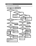
6-10) If the ice chute cover solenoid doesn’t work
Is the S/N(solenoid) for 0.3 sec
operated after 5 minutes from the outset
of power ON?
Start
Is MICOM No. 27 on
PCB maintaining High for 0.3 sec at the first
power ON?
Press Ice lever and keep it open.
Is the cover closed of
S/N after a lapse of about
7
∼
10 seconds?
With the ice S/W ON
and ICE S/W on, ice-movement motor in F room?
Does C-E(between C and E)
of TR Q701 turn ON for 0.3 sec?
MICOM control port is normal.
Exchange the main PCB assembly.
The S/N control PCB assembly and
wire system have no trouble.
All the control system of cover ice-
route has no trouble.
Check the ICE S/W and troubleshoot
the wire connection syste
m.
- Main PCB and the sensing section of
ice-S/W are normal.
- Check the operation of SSR71 and
Q701.
Check the stop lever and support
time-delay.
Replace TR Q701 check SSR71 after, and
then exchange failed components or replace
the PCB assembly.
TR701 and SSR71 are normal
YES
YES
NO
YES
YES
YES
YES
YES
NO
NO
NO
NO
NO
1) Check if the solenoid is operated unconditionally for 0.3 sec, independent of the Open/Close condition of cover ice-route,
after a lapse of about 5 seconds from the outset of power ON. (Before installation, the cancellation of cover ice-route Open is
enabled.)
2) Check if the connector of upper hinge section is hook-up correctly.
Preliminary check
Subject to the ice
S/W ON, do CN31 No. 2 and MICOM No. 45
get impressed 0V?
Summary of Contents for RS265 LAWP
Page 18: ...18 Refrigerator 2 PRODUCT SPECIFICATIONS 2 9 Cooling Air Circulation Freezer...
Page 70: ...70 8 BLOCK DIAGRAM...
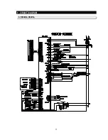
Page 71: ...71 9 CIRCUIT DIAGRAM 9 1 RS269LA RS267LA...
Page 72: ...72 9 CIRCUIT DIAGRAM 9 2 RS265LA...
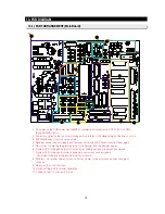
Page 74: ...74 10 PCB DIAGRAM 10 2 CONNECTOR ARRANGEMENT Main Board...


