30
4. ALIGNMENT AND ADJUSTMENTS
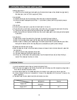
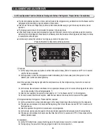
Self-diagnostics check list
If any LEDs blink, the corresponding sensors and
components must be checked for an error.
NO
Error
ICE MAKER SENSOR
REFRIGERATOR SENSOR
REFRIGERATOR DEFROST SENSOR
REFRIGERATOR FAN ERROR
ICE MAKER function error
CoolSelect Zone
TM
SENSOR
REFRIGERATOR DEFROST ERROR
EXIT-SENSOR
FREEZER SENSOR
FREEZER DEFROST ERROR
FREEZER FAN ERROR
CONDENSER FAN ERROR
FREEZER DEFROST ERROR
①
②
③
④
⑤
⑥
⑦
⑧
⑨
⑩
⑪
⑫
⑬
Air sensor connector missing; contact failure,
electric wire cut, short-circuit; open air sensor
itself failure; and so on
CoolSelect
Zone
TM
sensor
REFRIGERATOR
DEFROST ERROR
Ambient Air
SENSOR
The voltage should be within the range of 4.5V~1.0V
between MAIN PCB CN51 # 13 and # 14.
Read the resistance between the brown and the orange wire
terminals(the reading varies according to the basic Power Consumption.
0 Ohm
→
Heater Short,
∞
Ohm
→
Wire Cut or Blown Bimetal Thermo
The voltage should be within the range of 4.5V~1.0V
between MAIN PCB CN31 # 1 and # 4.
Freezer sensor connector missing; contact
failed, electric wire cut, short-circuit;Freezer
Room sensor itself failure.
FREEZER
SENSOR
The voltage should be within the range of 4.5V~1.0V
between MAIN PCB CN30 # 2 and # 3.
Freezer evaporator defrosting sensor connector
missing; contact failed, electric wire cut, short-
circuit; sensor itself failure; and so on
FREEZER
DEFROST SENSOR
The voltage should be within the range of 4.5V~1.0V
between MAIN PCB CN30 # 2 and # 4.
Freezer Fan motor operation failure; feedback
signal line contact failure, motor’s electric wire
missing; and so on.
FREEZER FAN
ERROR
The voltage should be 7V~12V between MAIN PCB CN72 #
6(YELLOW) and # 7(GRAY).
Condenser Fan motor operation failure; feedback
signal line contact failure, motor’s electric wire
missing; and so on.
In the freezer room, if frost removal mode is
finished due to limited time of 70 minutes. Error is
displayed
CONDENSER FAN
ERROR
(COMP-FAN)
The voltage should be 7V~12V between MAIN PCB CN72 #
4(S/BLUE) and # 7(GRAY).
Read the resistance between the white and the orange wire
terminals(the reading varies according to the basic Power Consumption.
0 Ohm
→
Heater Short,
∞
Ohm
→
Wire Cut or Blown Thermo Fuse
FREEZER
DEFROST ERROR
NO
Error items
LED Display
Details
How to Self-Diagnose
01
02
03
04
05
06
07
08
09
10
11
12
13
ICE MAKER
SENSOR
Ice Maker sensor connector missing; contact
failure, electric wire cut, short-circuit; Ice Maker
sensor failure; and so on
The voltage should be within the range of 4. 5V~1.0V
between MAIN PCB CN90 # 3 and # 4.
REFRIGERATOR
SENSOR
Refrigerator sensor connector missing; contact
failure, electric wire cut, short- circuit; Refrigerator
sensor itself failure; and so on
Refrigerator Fan motor operation failure;
feedback signal line contact failed, electric wire
cut, short- circuit; and so on
The voltage should be within the range of 4.5V~1.0V
between MAIN PCB CN30 # 6 and # 7.
The voltage should be within the range of 4.5V~1.0V between MAIN PCB
CN30 # 6 and # 8.Indicate Error when the temperature sensed by
Refrigerator defrosting sensor is higher than 150
℉
or lower than –58
℉
.
REFRIGERATOR
DEFROST SENSOR
Refrigerator evaporator internal defrosting sensor
connector missing; contact failure, electric wire cut,
short-circuit; sensor itself failure; and so on
The voltage should be 7V~12V between MAIN PCB CN72 #
5(ORANGE) and #7(GRAY).
Pusht het est b ut t ononanI / MAss' yandI tshoul d work.
REFRIGERATOR
FAN ERROR
ICE MAKER function
ERROR
Ice-ejector and level failed three times or more
Error items of self-diagnostics
CoolSelect Zone
TM
sensor connector missing; contact
failed, electric wire cut, short-circuit; CoolSelect Zone
TM
sensor itself failed; and so on.
In the refrigerator room, if frost removal mode is
finished due to limited time of 80 minutes. Error
is displayed.
Summary of Contents for RS265BBWP
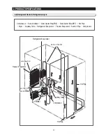
Page 18: ...18 Refrigerator 2 PRODUCT SPECIFICATIONS 2 9 Cooling Air Circulation Freezer...
Page 68: ...7 EXPLODED VIEW PARTS LIST 7 3 Cabinet 7 1 69...
Page 78: ...79 8 BLOCK DIAGRAM...
Page 79: ...80 9 WIRING DIAGRAM 9 1 RS265BB RS267BB RS267LB RS269LB...
Page 80: ...81 9 WIRING DIAGRAM 9 2 RS263BB RS265LB...
Page 82: ...83 10 PCB DIAGRAM 10 2 CONNECTOR ARRANGEMENT Main Board...
Page 83: ...84 11 CIRCUIT DIAGRAM...


