31
4. ALIGNMENT AND ADJUSTMENTS
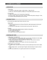
4-6) Restoration Function for Power Outage
4-7) Set Point Shift Function
※
For the REFRIGERATOR FAN, only one rpm is applied for the current models, so that
①
and
②
show
REFRIGERATOR FAN operation only.
※
The FREEZER FAN and CONDENSER FAN are operated to High/Low rpm automatically according to the
operational condition.
※
④⑤
and
⑥
only explain the system operation state according to the ambient condition
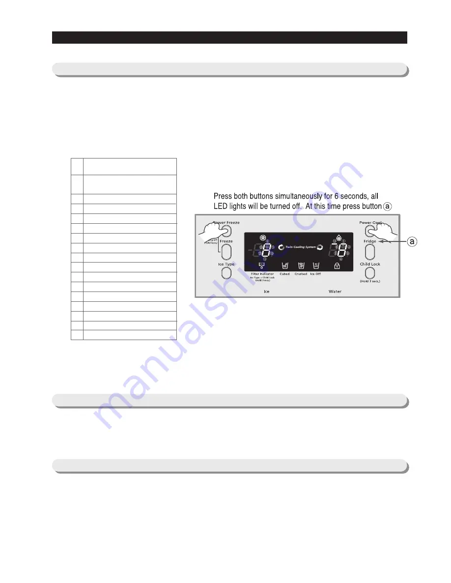
1) When the freezer temperature is lower than 41
℉
, all functions on the display panel will be restored.
2) When the freezer temperature is higher than 41
℉
, all functions will be initialized.
(-4
℉
for the freezer, 38
℉
for the refrigerator, and Cubed for the Ice Type)
●
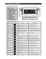
Press Freezer Temp. and Power Cool buttons simultaneously for 12 seconds to get into this mode.
●
In this mode, only the display LEDs for temperature will be ON.
NO
Contents
REFRIGERATOR FAN High or AC
motor operation
REFRIGERATOR FAN Low
REFRIGERATOR DEFROST heater
Start mode
Overload mode
Low-temperature mode
Exhibition mode
COMPRESSOR
FREEZER FAN High
FREEZER FAN Low
FREEZER DEFROST Heater
CONDENSER FAN High
CONDENSER FAN Low
Dispenser-Heater
Damper
Normal condition
Table of Load Mode Check List
①
②
③
④
⑤
⑥
⑦
⑧
⑨
⑩
⑪
⑫
⑬
⑭
⑮
-
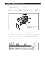
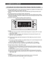
4-5) Load Operation Check Function
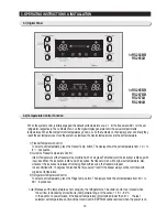
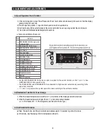
1) In the normal operation, press Power Freeze and Power Cool buttons simultaneously for 6 seconds, then the display
panel will blink for 2 seconds.
2) Press Fridge Temp. button
ⓐ
to get into this check mode with an audible tone.
3) Each illuminating LED segment stands for the component which has an ouput signal from the control board.
4) This mode will terminate automatically after 30 seconds.
Summary of Contents for RS265BBWP
Page 18: ...18 Refrigerator 2 PRODUCT SPECIFICATIONS 2 9 Cooling Air Circulation Freezer...
Page 68: ...7 EXPLODED VIEW PARTS LIST 7 3 Cabinet 7 1 69...
Page 78: ...79 8 BLOCK DIAGRAM...
Page 79: ...80 9 WIRING DIAGRAM 9 1 RS265BB RS267BB RS267LB RS269LB...
Page 80: ...81 9 WIRING DIAGRAM 9 2 RS263BB RS265LB...
Page 82: ...83 10 PCB DIAGRAM 10 2 CONNECTOR ARRANGEMENT Main Board...
Page 83: ...84 11 CIRCUIT DIAGRAM...

